| CPC A61C 5/88 (2017.02) | 23 Claims |

|
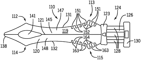
1. A dental wedge for creating space between adjacent teeth, the dental wedge comprising:
an elongated body extending from an outer end to an opposite inner end, the body comprising a longitudinal first side wall connected to a longitudinal second side wall, the first side wall and the second side wall each being spaced apart creating an inverted generally V-shaped transverse section for the body, the body having a top surface and a bottom surface,
wherein the body includes a region of increased flexibility compared to each of the first side wall and the second side wall,
wherein the region of increased flexibility comprises a throughhole in the body through the first side wall and the second side wall only at the inner end of the elongated body of the dental wedge, the throughhole extending from the top surface to the bottom surface,
wherein the inner end of the dental wedge at the longitudinal first side wall and at the longitudinal second side wall decreases in cross-section in a direction away from the outer end of the dental wedge to define a distal tip of the dental wedge, and
wherein the dental wedge includes a ridge defined between the longitudinal first side wall and the longitudinal second side wall, the ridge including a first portion and a second portion that are positioned on opposing sides of the throughhole, the first portion of the ridge extending along a central region of the dental wedge between the throughhole and the outer end, the second portion of the ridge being between the throughhole and the distal tip of the dental wedge at the inner end;
wherein when the dental wedge is inserted between adjacent teeth and the distal tip of the dental wedge contacts one or both of the adjacent teeth, the first side wall and the second side wall are configured to flex inward at the throughhole while being advanced between the adjacent teeth, and
wherein when the dental wedge is further inserted between the adjacent teeth with the first side wall and the second side wall flexed inward, the first side wall and the second side wall are configured to automatically expand at the throughhole when the throughhole is advanced past the adjacent teeth.
|