| CPC A61B 17/07207 (2013.01) [A61B 17/068 (2013.01); A61B 17/0682 (2013.01); A61B 17/072 (2013.01); A61B 17/105 (2013.01); A61B 17/07292 (2013.01); A61B 2017/00017 (2013.01); A61B 2017/0046 (2013.01); A61B 2017/00115 (2013.01); A61B 2017/00398 (2013.01); A61B 2017/00734 (2013.01); A61B 2017/00858 (2013.01); A61B 2017/07214 (2013.01); A61B 2017/07221 (2013.01); A61B 2017/07242 (2013.01); A61B 2017/07257 (2013.01); A61B 2017/07264 (2013.01); A61B 2017/07271 (2013.01); A61B 2017/07278 (2013.01); A61B 2090/038 (2016.02); A61B 2090/0811 (2016.02)] | 8 Claims |

|
1. A surgical end effector, comprising:
an elongate support comprising a proximal end, a distal end, and a length between the proximal end and the distal end, wherein the elongate support is configured to operably support a staple cartridge therein;
an anvil including a proximal anvil end, a distal anvil end, longitudinal rows of staple forming cavities, and an anvil length extending between the proximal anvil end and the distal anvil end, wherein the anvil comprises a longitudinal slot defined therein extending intermediate the longitudinal rows of staple forming cavities;
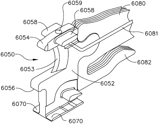
a knife member configured to translate between a starting position adjacent the proximal end of a bottom of the elongate support and an ending position adjacent the distal end of the bottom of the elongate support, wherein the knife member is retractable back into the starting position, and wherein the knife member comprises:
an anvil side;
a support side;
a distal end including an anvil cam configured to engage the anvil, a support cam configured to engage the elongate support, and a solid body extending between the anvil cam and the support cam; and
a flexible proximal end;
a first position indicator on the knife member, wherein the first position indicator is on the anvil side of the knife member; and
a second position indicator on the support side of the knife member, wherein the second position indicator comprises an opening in the proximal end of the elongate support, wherein the starting position of the knife member can be verified via at least one of the first position indicator and the second position indicator, wherein said first position indicator comprises a light source and wherein said second position indicator comprises a light source.
|