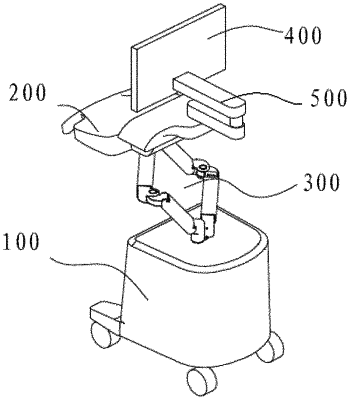
| CPC A61B 8/4405 (2013.01) [A61B 8/462 (2013.01); F16M 11/045 (2013.01); F16M 11/046 (2013.01); F16M 11/048 (2013.01); F16M 2200/047 (2013.01); F16M 2200/066 (2013.01)] | 11 Claims |

|
1. An ultrasound diagnostic apparatus comprising a main body, a control panel and a display, and further comprising a first connection rod assembly and a second connection rod assembly connected between a first component and a second component, wherein, the first component and the second component are any two of the control panel, the main body and the display, and each connection rod assembly comprises:
a first support seat connected to the first component through a sixth rotation pair and being able to be rotated around a sixth rotation axis relative to the first component through the sixth rotation pair;
a first connection arm, wherein one end of the first connection arm is connected to the first support seat through a first rotation pair and is able to be rotated around a first rotation axis relative to the first support seat through the first rotation pair;
a first connection seat, wherein the other end of the first connection arm is connected to the first connection seat through a second rotation pair and is able to be rotated around a second rotation axis relative to the first connection seat through the second rotation pair;
a second connection seat connected to the first connection seat through a third rotation pair and being able to be rotated around a third rotation axis relative to the first connection seat through the third rotation pair;
a second connection arm, wherein one end of the second connection arm is connected to the second connection seat through a fourth rotation pair and is able to be rotated around a fourth rotation axis relative to the second connection seat through the fourth rotation pair; and
a second support seat, wherein the other end of the second connection arm is connected to the second support seat through a fifth rotation pair and is able to be rotated around a fifth rotation axis relative to the second support seat through the fifth rotation pair;
wherein the second support seat is connected to the second component through a seventh rotation pair and is able to be rotated around a seventh rotation axis relative to the second component through the seventh rotation pair.
|