| CPC A61B 5/4504 (2013.01) [A61B 5/0048 (2013.01); A61B 5/05 (2013.01); G01B 7/16 (2013.01); G01B 7/24 (2013.01); G01D 5/202 (2013.01); G01D 5/2013 (2013.01); G01N 3/066 (2013.01); G01N 3/08 (2013.01); G01N 3/20 (2013.01); G01N 27/9006 (2013.01); G01N 27/9046 (2013.01); G01N 33/4833 (2013.01); H01Q 9/16 (2013.01); A61B 2562/0252 (2013.01); A61B 2562/14 (2013.01); G01N 2203/0023 (2013.01); G01N 2203/0032 (2013.01); G01N 2203/0076 (2013.01)] | 19 Claims |

|
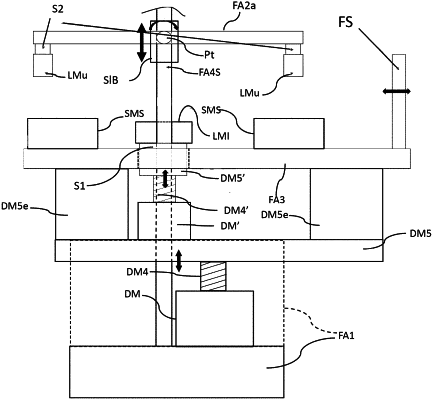
1. A loading device for measuring stiffness of a structural member (SM), the loading device comprising:
a frame assembly including:
a lower support restable on a stable support;
a distal frame movable with respect to the lower support;
a plurality of first loading members disposed spaced on the distal frame along a longitudinal direction of the distal frame and configured to support the SM;
a plurality of SM support members disposed spaced on the lower support along a longitudinal direction of the lower support and configured to support the SM; and
at least one second loading member disposed between the plurality of SM support members and configured to be movable relative to the plurality of SM support members in a direction toward and away from the distal frame;
a first driving mechanism that moves the at least one second loading member to apply a load to the SM and create multiple bending points with respect to the plurality of first loading members and the at least one second loading member;
a first sensor that measures a load applied by the first driving mechanism to the at least one second loading member;
a plurality of second sensors that measure a first deflection of the SM undergoing loading;
a third sensor that measures a second deflection of the SM undergoing loading without using any strain sensing device attached to the SM or contacting the SM,
wherein the stiffness of the SM is determinable from:
a first slope of a first deflection curve obtained from the plurality of second sensors versus an applied load curve obtained from the first sensor; and
a second slope of a second deflection curve obtained from the third sensor versus the applied load curve.
|