| CPC A01F 15/0765 (2013.01) [A01F 15/18 (2013.01); A01F 2015/077 (2013.01); A01F 2015/183 (2013.01); A01F 2015/186 (2013.01)] | 9 Claims |

|
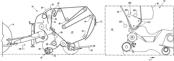
1. A bale chamber of an agricultural round baler, comprising:
a main frame;
a plurality of rollers supported by the main frame;
at least one belt engaging with at least one roller of the plurality of rollers, and the at least one belt and the plurality of rollers are together configured for creating a round circulating chamber which expands in between an empty bale position and a full bale position for engaging and rolling a bale;
a subframe movably connected to the main frame;
at least one follower roller pivotally connected to the subframe at a first pivot axis, the at least one follower roller engaging with the at least one belt, and the subframe is configured for moving during formation of the bale so that the at least one follower roller moves in between a first position at the empty bale position of the circulating chamber and a second position at the full bale position of the circulating chamber, the subframe comprising a pair of mounting plates which are pivotally connected to the main frame, the mounting plates of the subframe each have a triangular cross-section with a top portion which is pivotally connected to the main frame at a second pivot axis and a base portion which pivotally mounts the at least one follower roller at the first pivot axis, the at least one follower roller comprises two follower rollers which are respectively pivotally connected to opposing ends of the base portion of each mounting plate of the subframe; and
a first mechanical stop and a second mechanical stop configured for contacting and limiting a movement of the subframe, the first mechanical stop is located rearwardly of the subframe, and the second mechanical stop is located forwardly of the subframe, the first and second mechanical stops being adjustably mounted in indexed positions on the main frame.
|
|
4. An agricultural round baler, comprising:
a pickup unit configured for picking up a crop material from a field; and
a bale chamber configured for receiving the crop material from the pickup unit, comprising
a main frame;
a plurality of rollers supported by the main frame;
at least one belt engaging with at least one roller of the plurality of rollers, and the at least one belt and the plurality of rollers are together configured for creating a round circulating chamber which expands in between an empty bale position and a full bale position for engaging and rolling a bale;
a subframe movably connected to the main frame;
at least one follower roller pivotally connected to the subframe at a first pivot axis, the at least one follower roller engaging with the at least one belt, and the subframe is configured for moving during formation of the bale so that the at least one follower roller moves in between a first position at the empty bale position of the circulating chamber and a second position at the full bale position of the circulating chamber, the subframe comprising a pair of mounting plates which are pivotally connected to the main frame, the mounting plates of the subframe each have a triangular cross-section with a top portion which is pivotally connected to the main frame at a second pivot axis and a base portion which pivotally mounts the at least one follower roller at the first pivot axis, the at least one follower roller comprises two follower rollers which are respectively pivotally connected to opposing ends of the base portion of each mounting plate of the subframe; and
a first mechanical stop and a second mechanical stop configured for contacting and limiting a movement of the subframe, the first mechanical stop is located rearwardly of the subframe, and the second mechanical stop is located forwardly of the subframe, the first and second mechanical stops being adjustably mounted in indexed positions on the main frame.
|
|
7. A method of operating an agricultural round baler, comprising:
providing a bale chamber for the agricultural round baler, the bale chamber comprising a main frame, a plurality of rollers supported by the main frame, at least one belt engaging with at least one roller of the plurality of rollers, and the at least one belt and the plurality of rollers are together configured for creating a round circulating chamber which expands in between an empty bale position and a full bale position for engaging and rolling a bale, a subframe movably connected to the main frame, and at least one follower roller pivotally connected to the subframe at a first pivot axis, the at least one follower roller engaging with the at least one belt;
rolling the bale within the circulating chamber; and
moving the subframe during formation of the bale so that the at least one follower roller moves in between a first position at the empty bale position of the circulating chamber and a second position at the full bale position of the circulating chamber, the subframe comprising a pair of mounting plates which are pivotally connected to the main frame, the mounting plates of the subframe each have a triangular cross-section with a top portion which is pivotally connected to the main frame at a second pivot axis and a base portion which pivotally mounts the at least one follower roller at the first pivot axis, the at least one follower roller comprises two follower rollers which are respectively pivotally connected to opposing ends of the base portion of each mounting plate of the subframe, a first mechanical stop and a second mechanical stop configured for contacting and limiting a movement of the subframe, the first mechanical stop is located rearwardly of the subframe, and the second mechanical stop is located forwardly of the subframe, the first and second mechanical stops being adjustably mounted in indexed positions on the main frame.
|