| CPC H02M 3/1584 (2013.01) [B60L 3/00 (2013.01); B60L 50/40 (2019.02); B60L 50/50 (2019.02); B60R 16/033 (2013.01); H02M 1/32 (2013.01); H02M 1/36 (2013.01); H02M 1/0009 (2021.05)] | 4 Claims |

|
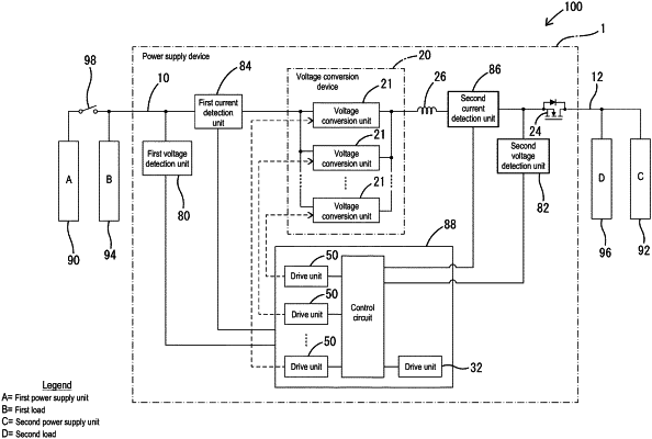
1. An in-vehicle power supply device configured to lower a voltage applied to a first conductive path that is electrically connected to a capacitive component and apply the resultant voltage to a second conductive path, or boost a voltage applied to the second conductive path and apply the resultant voltage to the first conductive path,
the in-vehicle power supply device comprising:
a first voltage conversion unit that includes a first drive switching element, a second drive switching element, and a first inductor, performs a first voltage conversion operation in which a voltage applied to the first conductive path is lowered and an output voltage is applied to the second conductive path, in accordance with a first control signal, in which an ON signal and an OFF signal are alternately switched, being supplied to the first drive switching element, and performs a third voltage conversion operation in which a voltage applied to the second conductive path is boosted and an output voltage is applied to the first conductive path in accordance with a third control signal, in which an ON signal and an OFF signal are alternately switched, being supplied to the second driving switching element;
a reverse-flow prevention switching element that is provided on the second conductive path and that interrupts a flow of a current on the second conductive path toward the first voltage conversion unit when turned OFF;
a second inductor that is provided between the first voltage conversion unit and the reverse-flow prevention switching element on the second conductive path, and in series with respect to the reverse-flow prevention switching element;
a semiconductor element part constituted by a diode or a switching element that has one end electrically connected to the second inductor and the reverse-flow prevention switching element on the second conductive path and another end electrically connected to a reference conductive path; and
a control unit that outputs the first control signal to at least the first drive switching element, and outputs the third control signal to the second drive switching element, wherein
a plurality of the first voltage conversion units are connected in parallel with each other between the first conductive path and the second conductive path,
a second voltage conversion unit is configured by including the reverse-flow prevention switching element, the second inductor, and the semiconductor element part, and, when a part of the second conductive path that is on the first voltage conversion unit side of the second voltage conversion unit is regarded as an output-side conductive path, and a part of the second conductive path that is on the side opposite to the first voltage conversion unit side is regarded as an input-side conductive-path, the second voltage conversion unit performs the second voltage conversion operation in which the voltage applied to the input-side conductive path is lowered, and an output voltage is applied to the output-side conductive path,
the control unit being configured to cause the second voltage conversion unit to perform the second voltage conversion operation in accordance with a predetermined precharge condition being satisfied, by applying a second control signal, in which an ON signal and an OFF signal are alternately switched, to the reverse-flow prevention switching element, and
upon starting the second voltage conversion operation, the control unit supplies the third control signal to only some of the plurality of the first voltage conversion units in accordance with a predetermined switching condition being fulfilled, thereby causing some of the first voltage conversion units to perform the third voltage conversion operation.
|