| CPC H02J 3/06 (2013.01) [G01R 19/2513 (2013.01); G01R 21/133 (2013.01); H02J 3/00 (2013.01); H02J 2203/20 (2020.01)] | 7 Claims |

|
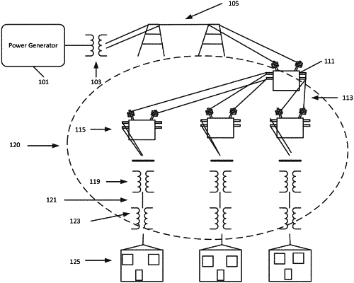
1. A method for load flow analysis of a power distribution system including, in electrical connection, an electricity generation plant, an electricity transmission grid, and an electricity distribution grid having a plurality of power distribution lines, wherein the power distribution system is configured as a radial network having a plurality of buses, the plurality of power distribution lines, and at least one of the buses has a link to at least two of the power distribution lines, the method performed by processing circuitry configured to:
receive a Branch Matrix (BM) having a row for each power distribution line and a column for each bus, wherein the BM contains values indicating buses and associated power distribution lines;
iteratively determine currents for the plurality of power distribution lines and voltages across each of the buses until a difference between a bus voltage and a previous iterated bus voltage at each bus is below a predetermined tolerance; and
display a graph of bus voltages for each bus as a voltage profile,
wherein
the circuitry iteratively determines the currents by
determining an initial current matrix (CM′) using the BM by multiplying a node current with corresponding matrix elements in the BM, wherein the node current is a ratio of a complex power at a bus and a voltage of the bus; and
determining the currents for the plurality of power distribution lines in a zig zag manner over the matrix elements in the CM′ and records the determined currents in a final current matrix (CM);
the circuitry iteratively determines the voltages by
determining the voltage across each bus based on a voltage drop between buses, starting from buses upstream and moving to buses downstream in the direction of voltage flow.
|