| CPC H01F 21/04 (2013.01) [G01D 5/2291 (2013.01); H01F 27/02 (2013.01); H01F 27/28 (2013.01); H01F 41/02 (2013.01)] | 9 Claims |

|
1. A rotary variable differential transformer for measuring angular displacement of a shaft, the rotary variable differential transformer comprising:
a stator housing:
a primary coil configured to receive an alternating current;
a first secondary coil electromagnetically coupled to the primary coil; and
a second secondary coil electromagnetically coupled to the primary coil; and
a rotor positioned concentrically within the stator, wherein the rotor is configured to receive a shaft and rotate with the shaft while the stator remains stationary;
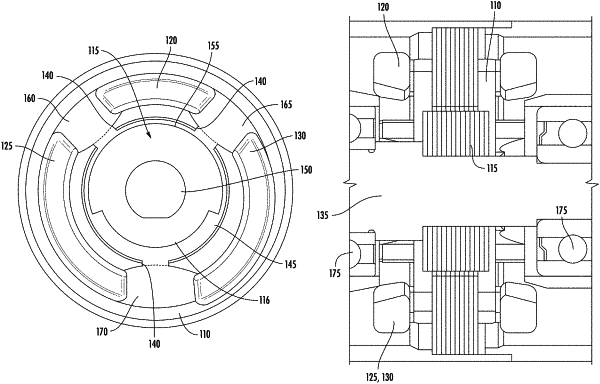
wherein the primary coil is positioned at a first radial position within the stator spaced between about 90 to 150 degrees from each of the first secondary coil and the second secondary coil;
wherein the rotor is configured with a magnetically permeable arcuate section extending from 180 to 270 degrees of the entire circumference of the rotor, such that 90 to 150 degrees of the circumference of the rotor defines a base portion having a smaller radius than the magnetically permeable arcuate section; and
wherein the stator further defines an airgap between 0.001 and 0.010 inches measured between the stator and the rotor.
|