| CPC F02B 37/24 (2013.01) [F16B 17/006 (2013.01)] | 13 Claims |
|
1. A nozzle device, comprising:
an annular nozzle plate;
an annular nozzle mount defining a nozzle flow passage between the nozzle mount and one surface of the nozzle plate;
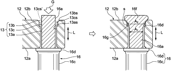
at least one nozzle support coupling the nozzle plate and the nozzle mount, and fixed to at least the nozzle plate by caulking; and
at least one nozzle vane supported between the nozzle plate and the nozzle mount,
wherein the nozzle plate has a through hole into which an end portion of the at least one nozzle support is inserted, and
wherein the through hole includes:
a straight portion extending from the one surface toward another surface of the nozzle plate;
an enlarged diameter portion formed on a side of the another surface of the nozzle plate and having a larger diameter than the straight portion; and
a relief processing portion which is formed in a part of the straight portion continuing into the enlarged diameter portion and has a larger diameter than another part of the straight portion where the relief processing portion is not formed, the relief processing portion having a constant diameter and extending along an extending direction of the through hole.
|