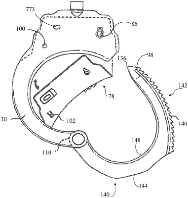
| CPC E05B 75/00 (2013.01) [E05B 15/0046 (2013.01)] | 22 Claims |

|
1. A personal restraint cuff, comprising:
a first cheek frame half including a first cheek arm and a first lockset cavity portion;
a second cheek frame half including a second cheek arm and a second lockset cavity portion, said first lockset cavity portion and said second lockset cavity portion combining to form a lockset cavity between the first and second cheek frame halves when the first and second cheek frame halves are secured to each other;
a bow having outwardly facing teeth along a portion of the bow and the bow being rotatably mounted to the first and second cheek arms; and
a lockset assembly removably disposed within the lockset cavity, the lockset assembly comprising:
a movable pawl having a first edge and an opposing second edge, the first edge of the pawl releasably engaging the teeth of the bow when the bow is rotated into engagement with the lockset assembly; and
a slidable lock bar facing the second edge of the pawl and having a plurality of projections separated by spaces between them; and
a button attached directly to one end of the lock bar, the button being installable and removable from the lockset assembly while the lockset assembly is disposed within the lockset cavity, and a distal end of the button extending out of the lockset cavity and being exposed to a user along combined edges of the first and second cheek frame halves when the lock bar is not in a double lock position, so that the user may push in the distal end of the button, sliding the lock bar into the double lock position;
wherein at least one of the projections of the lock bar abuts a respective projection on the second edge of the pawl when the lock bar is in the double lock position, preventing movement of the pawl and preventing rotation of the bow when the bow is engaged with the lockset assembly; and
wherein, when the lock bar is not in the double lock position, none of the plurality of projections of the lock bar abuts a respective projection on the second edge of the pawl, and the lock bar does not prevent movement of the pawl or rotation of the bow.
|