| CPC B64C 13/28 (2013.01) [B64C 9/02 (2013.01); B64C 9/22 (2013.01)] | 11 Claims |

|
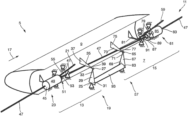
11. An aircraft comprising a wing, the wing comprising
a main wing;
a slat; and
a connection assembly movably connecting the slat to the main wing, such that the slat is movable between a retracted position and at least one extended position, the connection assembly comprising:
a first connection station comprising:
a first linkage pivotally mounted to the main wing via a first joint and pivotally mounted to the slat via a second joint;
a first slat track that is guided at the main wing for movement along a predefined path, and that is pivotally mounted to the slat via a third joint; and
a first drive station including a first input section coupled to a drive shaft, a first output section drivingly coupled to the first slat track, and a first gear unit coupled between the first input section and the first output section;
a second connection station spaced apart from the first connection station in a wing span direction, the second connection station comprising:
a second linkage pivotally mounted to the main wing via a fourth joint and pivotally mounted to the slat via a fifth joint;
a second slat track that is guided at the main wing for movement along a predefined path, and that is pivotally mounted to the slat via a sixth joint; and
a second drive station including a second input section coupled to the drive shaft, a second output section drivingly coupled to the second slat track, and a second gear unit coupled between the second input section and the second output section; and
a sync shaft attached at a first end to the first linkage and attached at a second end to the second linkage such that the sync shaft, the first linkage, and the second linkage are coupled in rotation for sync movement of the first and second connection stations.
|