| CPC H05K 7/18 (2013.01) [H05K 7/1485 (2013.01)] | 19 Claims |

|
1. An apparatus for protecting datacenter electronic components from water damage, the apparatus comprising:
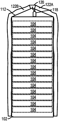
a server rack comprising a baffle configured to direct water incident on a top end of the server rack towards a front side of the server rack and a back side of the server rack;
datacenter electronic components mounted in the server rack;
a gas supply;
a front-side deployable water barrier attached to a top end of the server rack and having a stowed configuration and a deployed configuration, wherein the front-side deployable water barrier reconfigures from the stowed configuration to the deployed configuration when filled with gas from the gas supply to extend exterior to and along a front side of the server rack from the top end of the server rack to a bottom end of the server rack to block water ingress into the server rack through the front side of the server rack;
a back-side deployable water barrier attached to the top end of the server rack and having a stowed configuration and a deployed configuration, wherein the back-side deployable water barrier reconfigures from the stowed configuration to the deployed configuration when filled with gas from the gas supply to extend exterior to and along a back side of the server rack from the top end of the server rack to the bottom end of the server rack to block water ingress into the server rack through the back side of the server rack;
a sensor configured to detect occurrence of water incident on the server rack; and
a controller coupled with the sensor and the gas supply, wherein the controller is configured to cause the gas supply to supply the gas to each of the front-side deployable water barrier and the back-side deployable water barrier in response to the sensor detecting occurrence of water incident on the server rack.
|
|
5. An apparatus, comprising:
a deployable water barrier attached to a top end of a server rack and having a stowed configuration and a deployed configuration, wherein the deployable water barrier in the deployed configuration extends exterior to a side of the server rack from the top end of the server rack along a height of the server rack to block water ingress into the server rack;
a barrier deployment mechanism coupled to the deployable water barrier and operable to reconfigure the deployable water barrier from the stowed configuration to the deployed configuration via inflation of the deployable water barrier; and
a controller operatively coupled with a sensor and the barrier deployment mechanism, wherein the controller is configured to cause the barrier deployment mechanism to inflate the deployable water barrier in response to a signal, generated by the sensor, indicative of water incident on the server rack.
|
|
14. A method, comprising:
receiving a signal indicative of incidence of water in a region surrounding a server rack housing electronic components; and
in response to receiving the signal, reconfiguring a deployable water barrier via inflation of the deployable water barrier from a stowed configuration to a deployed configuration in which the deployable water barrier extends exterior to and along a height of the server rack to block water ingress into the server rack, wherein the deployable water barrier is attached to a top end of the server rack and extends from the top end of the server rack in the deployed configuration.
|