| CPC H01L 21/67393 (2013.01) [H01L 21/02 (2013.01); H01L 21/67 (2013.01); H01L 21/673 (2013.01); H01L 21/6732 (2013.01)] | 4 Claims |

|
1. A container for storing a wafer, the container comprising:
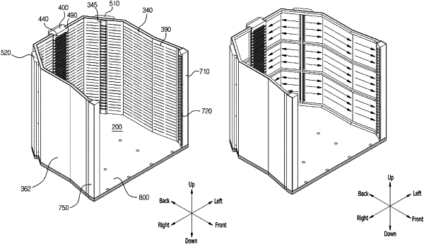
a storage chamber configured such that a wafer is stored therein through a front opening, wherein the storage chamber is divisible into a first purging area, and a second purging area provided above the first purging area in a vertical direction;
a first injection member inner wall surface in which a plurality of first injection holes are formed, and constituting a circumferential surface of the storage chamber;
a first injection member outer wall surface provided spaced from the first injection member inner wall surface in a direction opposite to the storage chamber;
a 1st-1st injection member provided in communication with a left side of the first purging area;
a 1st-2nd injection member provided in communication with the left side of the first purging area and provided adjacent side to the 1st-1st injection member;
a 2nd-1st injection member provided above the 1st-1st injection member and provided in communication with a left side of the second purging area; and
a 2nd-2nd injection member provided above the 1st-2nd injection member, provided in communication with the left side of the second purging area, and provided adjacent side to the 2nd-1st injection member,
wherein the 1st-1st, 1st-2nd, 2nd-1st, and 2nd-2nd injection members are defined by a first gap between the first injection member inner wall surface and the first injection member outer wall surface,
wherein the 1st-1st and 1st-2nd injection members are vertically partitioned so as to be positioned in a horizontal direction from each other,
wherein the 2nd-1st and 2nd-2nd injection members are vertically partitioned so as to be positioned in the horizontal direction from each other,
wherein the 1st-1st and 1st-2nd injection members are horizontally partitioned with the 2nd-1st and 2nd-2nd injection members so as to be positioned with the 2nd-1st and 2nd-2nd injection members in a vertical direction, and
wherein the 1st-1st, 1st-2nd, 2nd-1st, and 2nd-2nd injection members are independently supplied with a purge gas by different first external supply lines and supply the purge gas to the storage chamber through different first injection holes among the plurality of first injection holes.
|