| CPC F25D 25/027 (2013.01) [F25D 23/069 (2013.01); F25D 25/022 (2013.01); F25D 25/024 (2013.01); F25D 2325/021 (2013.01); F25D 2325/023 (2013.01)] | 19 Claims |

|
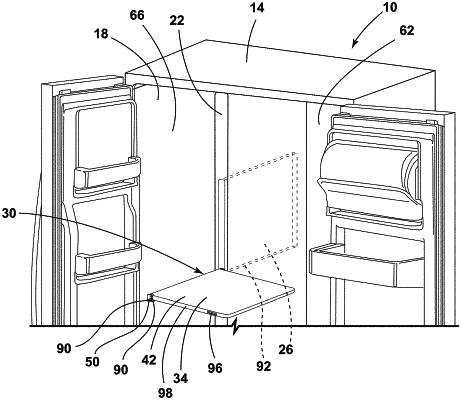
1. An appliance, comprising:
a cabinet;
an inner liner coupled to the cabinet;
a mullion coupled to the inner liner and defining a retaining space; and
a support assembly selectively disposed within the retaining space, the support assembly comprising:
a support surface operably coupled to the cabinet, the support surface configured to transition between a stowed position, a first deployed position, and a second deployed position, wherein the support surface comprises a first side and a second side;
a first retention feature operably coupled to the support surface;
a second retention feature operably coupled to the support surface at an opposing end from the first retention feature, wherein the second retention feature is coupled to an end of the support surface, and wherein the second retention feature is configured to rotate about an axis relative the cabinet; and
a bracket coupled to the support surface, wherein the bracket is disposed along a length of the support surface, wherein the bracket includes a first flange and a second flange, wherein the bracket enables rotation of the support surface in a first direction that corresponds with the first deployed position and a second direction that corresponds with the second deployed position, wherein the first side of the support surface contacts the first flange when the support surface is in the first deployed position, wherein the second side of the support surface contacts the second flange when the support surface is in the second deployed position, wherein the support surface extends beyond the first flange when the support surface is in the first deployed position, and wherein the support surface extends beyond the second flange when the support surface is in the second deployed position.
|