| CPC F16H 57/0482 (2013.01) [F16H 1/28 (2013.01); F16H 57/043 (2013.01); F16H 57/0427 (2013.01); F05D 2260/40311 (2013.01)] | 11 Claims |
|
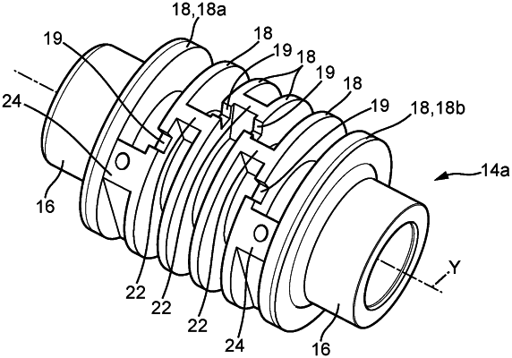
1. A reduction gear for a gas turbomachine with a longitudinal axis, comprising:
a ring gear and planet gears (8) engaged with a sun gear (7) and with the ring gear (9) each mounted free in rotation about their axis (Y) on a planet carrier (10),
each of the planet gears (8) being configured to rotate about their axis (Y) through a pivot (14) which comprises a first annular part (14a) including a lubrication axial passage (17) and a second annular part (14b) mounted around the first annular part (14a), the first annular part (14a) delimiting with the second annular part (14b) a lubrication circuit at least one oil inlet (20) of which opens out inwards of the first annular part (14a) into the axial passage (17) and at least one oil outlet (28) of which opens radially outwards of the second annular part (14b),
the first annular part (14a) comprising an annular wall (15) delimiting the axial passage (17) therein, the axial passage (17) being tubular and coaxial with the axis (Y) of the pivot.
|