| CPC F01D 17/162 (2013.01) [F01D 9/041 (2013.01); F05D 2260/79 (2013.01)] | 20 Claims |

|
1. A variable vane mechanism comprising:
a casing;
an actuator ring having an annular body defined about a main axis, the actuator ring being rotationally mounted to the casing for rotation about the main axis;
a set of vanes including a plurality of vanes circumferentially distributed about the main axis, each vane of the set of vanes having a vane axis extending from an inner end to an outer end, the inner end and the outer end being rotationally mounted to the casing to allow rotation of the corresponding vane about the vane axis, the vane axes extending non-parallel to the main axis, each vane having a vane arm with a vane arm length extending transversally to the vane axis;
a plurality of pins circumferentially distributed about the main axis, each pin extending along a pin axis from a first one of the actuator ring and a corresponding one of the vane arms;
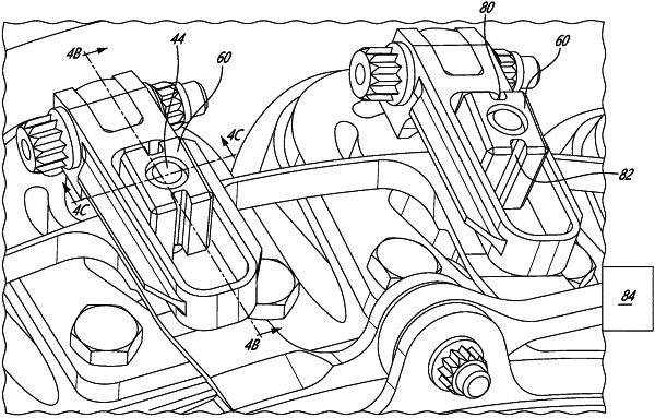
a plurality of slide blocks, each slide block rotationally mounted to a corresponding one of said plurality of pins for rotation about the pin axis, each slide block having two slide block faces facing transversally opposite sides relative to the pin axis, the two slide block faces being planar and parallel to one another; and
a plurality of guide slots, each guide slot defined by a second one of the actuator ring and the corresponding one of the vane arms, each guide slot having two guide slot faces that are planar and parallel to one another and a length extending away from a corresponding vane axis, each guide slot slidingly receiving a corresponding one of the slide blocks with each corresponding one of the slide block faces slidingly received by a corresponding one of the guide slot faces of the corresponding guide slot;
wherein each of the plurality of slide blocks is retained on the corresponding one of said plurality of pins along an orientation of the corresponding pin axis by a resilient retaining ring, the retaining ring extending partially into a slot defined around the corresponding one of said plurality of pins and partially into a slot defined around a central aperture of each of the plurality of slide blocks.
|