| CPC C21D 9/0056 (2013.01) [B65H 20/14 (2013.01); C21D 9/63 (2013.01); F27B 9/2476 (2013.01); F27B 9/28 (2013.01); B65H 2406/11325 (2013.01); B65H 2701/173 (2013.01)] | 13 Claims |

|
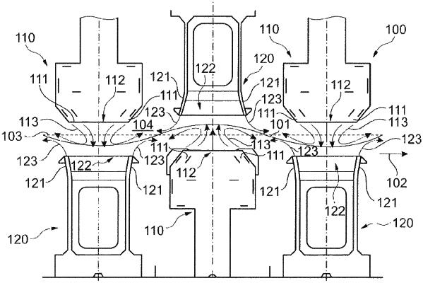
1. A strip flotation furnace (100) for controlling the temperature of a metal strip (101), the strip flotation furnace (100) comprising:
a plurality of flotation nozzle bars (110), each flotation bar of the plurality of flotation bars extending through the strip flotation furnace (100) transversely to a strip running direction (102) of the metal strip (101),
wherein each flotation nozzle bar (110) of the plurality of flotation bars has two opposing first rows of flotation nozzles (111), which are spaced apart by a central region (112) of the flotation nozzle bar (110),
wherein the rows of flotation nozzles (111) are configured in such a way that corresponding flotation nozzle jets (113), with a directional component in the direction of the central region (112), can be generated in order to provide pressure cushioning for guiding the metal strip (101),
a plurality of temperature-control nozzle bars (120) having a smaller nozzle exit area than the flotation nozzle bars, each temperature-control nozzle bar of the plurality of temperature-control nozzle bars extending transversely to a strip running direction (102) of the metal strip (101) and is spaced apart from a corresponding flotation nozzle bar (110) along the strip running direction (102),
wherein each temperature-control nozzle bar (120) of the plurality of temperature-control nozzle bars has two opposing additional rows of temperature-control nozzles (121), which are spaced apart by an additional central region (122) of the temperature-control nozzle bar (120),
wherein the rows of temperature-control nozzles (121) are configured in such a way that corresponding temperature-control nozzle jets (123), with a directional component in the opposite direction to the additional central region (122), can be generated to temperature control the metal strip as the metal strip is being guided,
wherein at least one temperature-control nozzle bar (120) is arranged between two flotation nozzle bars (110) spaced apart in the strip running direction (102),
wherein a temperature-control zone (104), by means of which the metal strip (101) may be conveyed, is formed within the strip flotation furnace (100),
wherein the flotation nozzle bars (110) are arranged above and below the temperature-control zone (104),
wherein upper flotation nozzle bars (110) are arranged so as to be offset from lower flotation nozzle bars (110) in the strip running direction (102),
wherein a temperature-control nozzle bar (120) is arranged opposite to a flotation nozzle bar (110) with respect to the temperature-control zone (104), and
wherein the lower flotation nozzle bars and lower temperature-control nozzle bars are arranged alternately along the strip running direction and the upper flotation bars and upper temperature-control nozzle bars are arranged alternately along the strip running direction.
|