| CPC A61M 39/285 (2013.01) | 17 Claims |

|
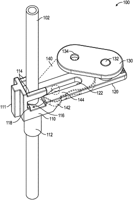
1. A flow stop assembly configured to control flow through a tubing, the flow stop assembly comprising:
a flow stop base comprising:
a base wall extending from the flow stop base;
at least one pincher guard, wherein the at least one pincher guard is configured to be disposed around the tubing;
a tubing guide configured to receive the tubing, wherein the at least one pincher guard and the tubing guide are axially spaced apart and are configured to axially align the tubing through the flow stop base;
a pincher recess defined between the base wall, the at least one pincher guard, and the tubing guide;
a pincher protrusion disposed within the pincher recess and configured to be adjacent to the tubing, wherein the pincher protrusion extends from the base wall; and
a base extension extending away from the pincher recess and defining a guide slot;
a pincher movable relative to the base extension and comprising a pincher surface and a guide pin extending through the guide slot, the pincher configured to move between a flow position and an occlusion position, wherein in the flow position the pincher surface is spaced apart from the pincher protrusion and in the occlusion position, the pincher surface is disposed adjacent to the pincher protrusion and is configured to obstruct flow through the tubing; and
a rocker rotatably coupled to the base extension and the pincher, wherein rotation of the rocker moves the pincher and the pincher is rotatable about the rocker in a first rotational axis and the guide pin in a second rotational axis different from the first rotational axis.
|