| CPC H03F 1/0288 (2013.01) [H02M 7/48 (2013.01); H03F 1/0277 (2013.01); H03F 3/19 (2013.01); H03F 3/21 (2013.01)] | 31 Claims |

|
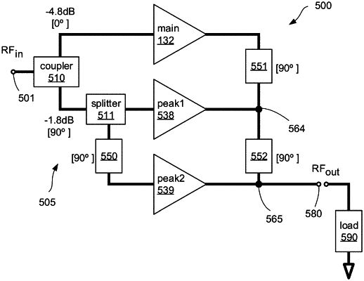
1. A power amplifier comprising:
a main amplifier having a main output coupled to a first node;
a first peaking amplifier having a first output coupled to the first node;
a first impedance inverter connected between the first node and a second node; and
a second peaking amplifier having a second output coupled to the second node, wherein:
no impedance inverter is connected between the second output of the second peaking amplifier and the second node;
the main amplifier, first peaking amplifier, and second peaking amplifier are in three parallel circuit branches;
a maximum power output by the main amplifier differs from a maximum power output by the first peaking amplifier and from a maximum power output by the second peaking amplifier such that a peak back-off efficiency for the power amplifier is less than 9.54 dB;
a load modulation ratio MR for the power amplifier comprises a ratio of an impedance seen by the main amplifier when the first peaking amplifier and the second peaking amplifier are fully backed-off to the impedance seen by the main amplifier when the first peaking amplifier and the second peaking amplifier are fully amplifying at the maximum power output; and
the MR for the power amplifier is equal to or less than 1.8.
|