| CPC H02P 7/0094 (2013.01) [H02P 7/2855 (2013.01); H03K 23/58 (2013.01)] | 10 Claims |
|
1. A motor control system comprising:
a controller configured to generate a variable supply voltage;
a direct current (DC) motor including a rotor induced to rotate in response to a drive current generated by the variable supply voltage, the rotation of the rotor generating a mechanical force that drives a component; and
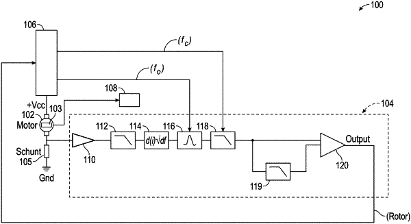
a ripple count circuit configured to filter the drive current based on a rotational speed (ω) of the rotor to generate at least one filtered drive current signal,
wherein the ripple count circuit includes a variable threshold unit configured to generate a varying threshold signal based on the at least one filtered drive current signal, and wherein the ripple count circuit generates a pulsed output signal indicative of the rotational speed (ω) of the rotor and a rotational position (θ) of the rotor based on a comparison between the at least one filtered drive current signal and the varying threshold signal,
wherein the ripple count circuit includes a downstream low pass filter disposed downstream from a bandwidth filter, the downstream low pass filter has a varying frequency cutoff that is actively set according to the rotational speed (ω) of the rotor and configured to eliminate harmonics from the at least one filtered drive current signal,
wherein the ripple count circuit compares the at least one filtered drive current signal to the varying threshold signal, outputs the pulsed output signal having a first output voltage level when a voltage level of the at least one filtered drive current is greater than or equal to the varying threshold signal, and outputs the pulsed output signal having a second output voltage level when a voltage level of the at least one filtered drive current is less than varying threshold signal.
|