| CPC H02H 9/041 (2013.01) [H01H 85/0039 (2013.01); H01H 85/0241 (2013.01); H01H 85/306 (2013.01); H01H 85/38 (2013.01); H01T 1/02 (2013.01); H01T 1/14 (2013.01); H01H 2085/381 (2013.01)] | 30 Claims |

|
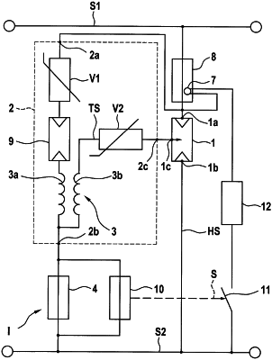
1. A lightning protection spark gap assembly having:
a lightning protection spark gap (1; 1′; 1″) having a first main connection (1a) and a second main connection (1b);
wherein a first voltage line (S1) of a supply network is connectable to the first main connection (1a) and a second voltage line of the supply network is connectable to the second main connection (1b);
a triggerable fusible link device (8) which is connectable between the first or second voltage line (S1, S2) and the corresponding main connection (1, 1b) of the lightning protection spark gap (1; 1′);
wherein at least one current path (TS; HS) leading via the lightning protection spark gap (1; 1′; 1″) is formable during operation between the first voltage line (S1) and the second voltage line (S2);
an indicator device (I; I′; IE) for capturing a current profile in the current path (TS; HS) or a corresponding portion of the current profile in the current path (TS; HS) and for triggering the fusible link device (8) with an electrical or mechanical delay when the captured current profile in the current path (TS; HS) or the corresponding portion of the current profile in the current path (TS; HS) satisfies a predefined criterion;
wherein the triggering of the fusible link device (8) is delayed by a predefined period which is selected in such a manner that a pulse current has substantially decayed before the fusible link device (8) is triggered;
wherein the fusible link device (8) has a bridge igniter (7) which is usable to trigger the fusible link.
|