| CPC H01H 1/20 (2013.01) [H01H 9/36 (2013.01); H01H 9/443 (2013.01); H01H 33/187 (2013.01); H01H 50/58 (2013.01); H01H 2009/365 (2013.01)] | 19 Claims |

|
1. A switching device, comprising:
a first fixed contact;
a second fixed contact;
a contact bridge;
a first movable contact and a second movable contact that are arranged at the contact bridge;
a first terminal contact on which the first fixed contact is mounted; and
a second terminal contact on which the second fixed contact is mounted,
wherein the first fixed contact is in contact with the first movable contact and the second fixed contact is in contact with the second movable contact in a switched-on state of the switching device,
wherein the first fixed contact is free of contact with the first movable contact and the second fixed contact is free of contact with the second movable contact in a switched-off state of the switching device,
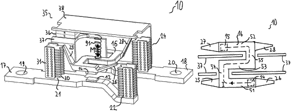
wherein a path of a load current that flows through the contact bridge between the first movable contact and the second movable contact in the switched-on state extends in a first plane,
wherein a movement of the contact bridge between the switched-on state and the switched-off state has a direction that is perpendicular to the first plane,
wherein the path of the load current that flows through the contact bridge between the first movable contact and the second movable contact in the switched-on state has at least one path in the first plane comprising an S-shaped path, a zig-zag path, a Z-shaped path, a C-shape, a path comprising two connected semicircles along the first plane, or a path twice curved in opposite directions along the first plane,
wherein a main direction of the first terminal contact is parallel to a main direction of the second terminal contact;
wherein a straight line running between the first movable contact and the second movable contact is across the main direction of the first terminal contact, and
wherein the load current, which flows through the first terminal contact, flows through a first arc, which is generated between the first fixed contact and the first movable contact at a transition between the switched-on state and the switched-off state of the switching device, flows through a first outer part of the contact bridge, and flows towards at least one of a first pair of arc runners associated with the first part of the contact bridge, has a U-form.
|