| CPC G01L 1/083 (2013.01) [G01M 1/14 (2013.01)] | 10 Claims |

|
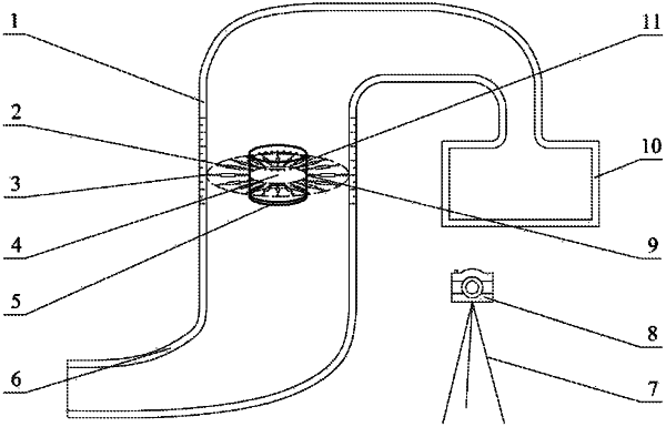
1. A measuring device for measuring an unbalanced moment of a bottom surface of a circular valve core, comprising:
a diverging shaped tube (6);
a water tank (10);
a transparent tube (1);
spring dynamometers (2);
laser sources (11);
a circular valve core (4); and
a high-speed camera (8),
wherein the circular valve core (4) is placed in the vertical transparent tube (1), positioning scales are marked on an outer wall of the transparent tube (1) and distributed along a length direction of the outer wall; a plurality of inner shackles (9) are evenly distributed on a side wall of the circular valve core (4) along a circumferential direction of the circular valve core (4), the inner shackles (9) are at the same height, and any pair of adjacent inner shackles (9) are spaced at equal angles, and each of the laser sources (11) are fixed on the side wall of the circular valve core (4) directly above a corresponding one of the inner shackles (9); the laser sources (11) directly above the inner shackles (9) are located at a same height of the side wall of the circular valve core (4), straight lines of laser emission directions of the respective laser sources (11) all pass through a circle center of a cross-section of the circular valve core (4) where all the laser sources (11) are located; outer shackles (3) respectively corresponding to the inner shackles (9) are evenly distributed on an inner wall of the transparent tube (1) along the circumferential direction, the outer shackles (3) and the inner shackles (9) are at a same height, and any pair of adjacent outer shackles (3) are spaced at equal angles, the inner shackles (9) and the outer shackles (3) are paired in pairs, and each pair of one inner shackle (9) and one outer shackle (3) are connected by a corresponding one of the spring dynamometers (2) that is tensioned;
when a central axis line of the circular valve core (4) coincides with a central axis line of the transparent tube (1) without tilting and twisting, all the spring dynamometers (2) are center-symmetrically distributed, and a tension force direction of each of the spring dynamometers (2) is parallel to the laser emission direction of a corresponding one of the laser sources (11) directly above it;
a tapered end of the diverging shaped tube (6) serves as a water inlet, and a diverging end is communicated with a bottom of the transparent tube (1), and there is no protrusion or depression at a joint between the diverging end and the bottom;
the high-speed camera (8) is movably placed outside of the transparent tube (1) and configured to surround the transparent tube (1) along the circumferential direction, to image postures of the circular valve core (4) and the spring dynamometers (2) in the tube at different orientations.
|