| CPC F21S 41/24 (2018.01) | 10 Claims |

|
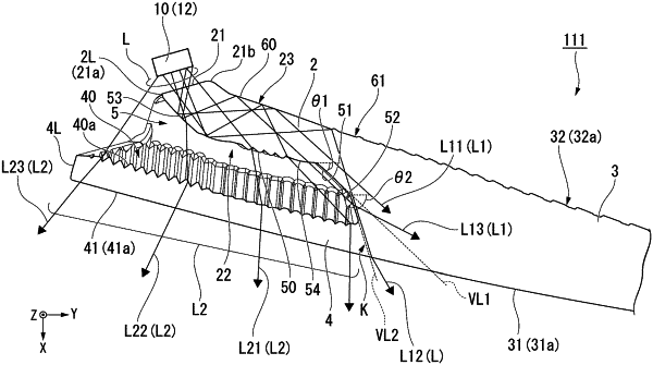
1. A vehicular lighting tool comprising:
a light source; and
a light guide lens configured to guide light from the light source,
wherein the light guide lens includes:
an introduction section into which light from the light source is introduced;
a light distribution section that is connected to the introduction section and that includes a light emitting surface which is configured to emit a first light introduced from the introduction section as illumination light;
a decoration section that is connected to the light distribution section and that includes a decoration-side emitting surface which is configured to emit a second light introduced from the introduction section as decoration light; and
a boundary portion that is located at a boundary between the light distribution section and the decoration section, and that includes a light emission surface which emits a third light introduced from the introduction section as a light in which occurrence of brightness unevenness has been minimized,
a slit section configured to separate the introduction section and the decoration section, and
the decoration section includes a decoration-side incidence surface that faces the introduction section and that is located at an emission direction side of the illumination light of the light distribution section,
the light emitting surface of the light distribution section and the decoration-side emitting surface are formed to be flush with each other so that a step difference is not generated between (a) the light emitting surface of the light distribution section and (b) the decoration-side emitting surface, and
the introduction section includes:
a light incidence surface which inputs light from the light source as light is introduced from the introduction section;
a lens cut that is configured to emit the second light input from the light incidence surface and that causes the second light to enter the decoration-side incidence surface via the slit section;
a first inclined surface that is located closer to the light distribution section than the lens cut and that is located on a tip side of the slit section;
a second inclined surface that connects the first inclined surface and the decoration section and that is located on the tip side of the slit section; and
a reflection cut surface that is provided on a surface opposite to the slit section, that is configured to reflect the third light entering from the light incidence surface and to emit from a boundary-side emitting surface,
wherein the second inclined surface is formed along a virtual line (VL2) extending toward the light emission surface of the boundary portion from the reflection cut surface.
|