| CPC F16N 39/002 (2013.01) [B01D 19/0031 (2013.01); B01D 45/14 (2013.01); F01D 25/20 (2013.01); F01M 2013/0422 (2013.01); F05D 2260/602 (2013.01); F05D 2260/98 (2013.01)] | 20 Claims |

|
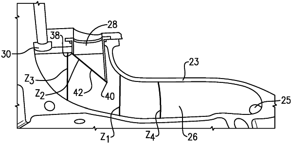
1. A gas and liquid separation system comprising:
a passage having an inlet connected to receive a mixed gas and liquid flow;
an air separation tube extending into said passage at a location downstream of where said inlet is connected with an upstream tube end upstream in said passage relative to a downstream tube end, said upstream tube end to provide an obstruction to the mixed gas and liquid flow, to cause separation of the gas from the mixed gas and liquid flow;
a liquid tube connected to said passage at a location downstream of the air separation tube;
wherein a fluid moving into the air separation tube opening will have a higher gas content than the mixed gas and fluid flow approaching the air separation tube, and a fluid flow entering said liquid tube will have a smaller percentage of gas than the mixed gas and fluid flow approaching the air separation tube;
wherein a first flow area is defined in the passage, upstream of the location where the air separation tube enters the passage a second flow area is defined at said end face of said air separation tube and a ratio of the first flow area to the second flow area is between 0.5 and 1.1; and
wherein a third flow area is defined in said passage at a location downstream of said air separation tube and a ratio of said first flow area to said third flow area is between 0.9 and 1.1, and a ratio of said second flow area to said third flow area is between 0.9 and 1.1.
|