| CPC F02M 51/061 (2013.01) [F02M 51/0614 (2013.01); F02M 51/0664 (2013.01); F02M 51/0685 (2013.01); F02M 61/16 (2013.01); F02M 47/027 (2013.01); F02M 51/00 (2013.01); F02M 51/02 (2013.01); F02M 51/0621 (2013.01); F02M 51/0628 (2013.01); F02M 51/0635 (2013.01); H01F 7/1638 (2013.01); H01F 7/1646 (2013.01); H02K 3/04 (2013.01)] | 20 Claims |

|
1. A fuel injection device comprising:
a valve body that comes into contact with a valve seat to close a fuel passage, and moves away from the valve seat to open the fuel passage in order to inject fuel through at least one injection orifice;
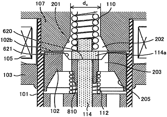
a mover that performs valve opening and closing operations in collaboration with the valve body, wherein the mover has a slope provided on an upper end surface of the mover and includes a through hole through which the valve body is inserted; and
a magnetic core that is excited by energization of a coil and that generates a magnetic force to drive the mover, wherein
the magnetic core has a hole that is opened in an end surface opposite to the mover and formed in a direction along a valve stem,
the hole has, provided on the mover side end surface of the magnetic core, a magnetic core inner diameter enlarged part in which an inner diameter is gradually enlarged from a back side of the hole toward the end surface opposite to the mover,
the magnetic core inner diameter enlarged part and the slope are located on an inner side of the magnetic core and an inner side of the mover, respectively,
in a region where the mover and the magnetic core face each other, the end of a face of the inner diameter enlarged part of the magnetic core and the end of an inner diameter side of a slope portion are provided at positions corresponding to each other, and
an interval between a surface where the magnetic core inner diameter enlarged part is formed and the slope of the mover in the direction along the valve stem is increased as the inner diameter of the inner diameter enlarged part becomes smaller.
|