| CPC F01P 3/2271 (2013.01) [F01P 11/0238 (2013.01)] | 16 Claims |

|
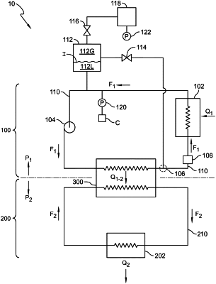
1. A cooling system including a vapor leak diversion system,
the cooling system comprising:
a first sealed cooling loop configured to operate at a first nominal working pressure, the first sealed cooling loop comprising:
a first fluid conduit;
a first coolant configured to circulate through the first fluid conduit, wherein the first coolant is a liquid at the first nominal working pressure;
a pump configured to circulate the first coolant through the first fluid conduit; and
a heat source configured to transfer heat to the first coolant;
a second sealed cooling loop configured to operate at a second nominal working pressure greater than the first nominal working pressure, the second sealed cooling loop comprising:
a second fluid conduit;
a second coolant configured to circulate through the second fluid conduit, wherein at least a portion of the second coolant is a liquid at the second nominal working pressure and wherein the second coolant is a vapor at the first nominal working pressure; and
a heat exchanger in fluid communication with the first sealed cooling loop and the second sealed cooling loop, the heat exchanger configured to exchange heat between the first sealed cooling loop and the second sealed cooling loop;
the first sealed cooling loop further comprising:
a coolant tank in fluid communication with the low-pressure side of the first sealed cooling loop, the coolant tank having a gas space configured to hold gas and a liquid space configured to hold a portion of the first coolant;
an inertial separator located between the heat exchanger and the heat source, the inertial separator configured to separate vapor from the first coolant;
a flow restrictor located between the inertial separator and the heat source; and
a heat source bypass pressure relief valve having an inlet in fluid communication with the inertial liquid and vapor separator and an outlet in fluid communication with the coolant tank, wherein the heat source bypass pressure relief valve is configured to open when a differential pressure between the inlet and the outlet of the heat source bypass pressure relief valve exceeds a first predetermined value;
wherein the flow restrictor and the pump cooperate to define a high-pressure side of the first cooling loop and a low-pressure side of the first sealed cooling loop.
|