| CPC F01D 11/02 (2013.01) [F16J 15/447 (2013.01); F05D 2220/31 (2013.01); F05D 2240/55 (2013.01)] | 10 Claims |

|
1. A rotating machine comprising:
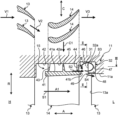
a casing having a hollow shape;
a rotating body rotatably supported in the casing;
a rotor blade fixed to an outer peripheral portion of the rotating body;
a stator blade arranged on a downstream side in a fluid flow direction with respect to the rotor blade and fixed to an inner peripheral portion of the casing;
a sealing device arranged between the inner peripheral portion of the casing and a tip of the rotor blade;
a swirling flow generation chamber provided in the casing on the downstream side in the fluid flow direction from the sealing device along a circumferential direction of the rotating body; and
a plurality of guiding members provided in the swirling flow generation chamber along a radial direction of the rotating body and in the circumferential direction of the rotating body at predetermined intervals, wherein
the swirling flow generation chamber has a wall surface on the downstream side in the fluid flow direction, the wall surface being located on the downstream side in the fluid flow direction from an edge portion of the stator blade on an upstream side in the fluid flow direction.
|