| CPC B60B 33/0092 (2013.01) [B62B 5/004 (2013.01); B62B 5/0069 (2013.01); B62B 5/04 (2013.01); B62B 2301/04 (2013.01)] | 8 Claims |

|
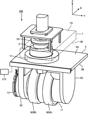
1. A driving wheel comprising:
a base portion;
a first shaft rotatably provided with respect to the base portion;
a rotation member rotatably provided around the first shaft;
a second shaft provided on the rotation member orthogonally to the first shaft;
a drive wheel provided at a position offset from a shaft center of the first shaft with respect to the rotation member and rotatable around the second shaft;
a drive unit provided on the rotation member and configured to rotationally drive the drive wheel;
a lock mechanism configured to turn into an unlock condition permitting rotation of the rotation member with respect to the base portion, and meanwhile, to turn into a lock condition deterring the rotation of the rotation member with respect to the base portion; and
a controller configured to control the drive unit and the lock mechanism,
wherein the controller is configured to control:
a first operation driving the drive unit while turning the lock mechanism into the lock condition;
a second operation driving the drive unit while turning the lock mechanism into the unlock condition, and rotating the rotation member around the first shaft along with the drive wheel; and
a third operation driving the drive wheel around the second shaft by an external force while turning the lock mechanism into the unlock condition, and rotating the rotation member around the first shaft along with the drive wheel; and
further comprising a driven wheel and a brake mechanism configured to brake rotation of the driven wheel,
wherein the controller is configured to control the brake mechanism to turn the brake mechanism into a brake-release condition in the first operation, turn the brake mechanism into a brake condition in the second operation, and turn the brake mechanism into the brake-release condition in the third operation.
|