| CPC B01D 53/1475 (2013.01) [B01D 53/002 (2013.01); B01D 2251/306 (2013.01); B01D 2251/606 (2013.01); B01D 2257/50 (2013.01); B01D 2258/0283 (2013.01); F23J 2215/50 (2013.01)] | 23 Claims |

|
1. A CO2 capture system with a gas turbine, comprising:
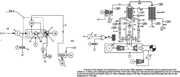
an inlet line arranged downstream of a CO2-rich flue gas source and conveying a CO2-containing initial flue gas flow to a compressor portion of said gas turbine for compressing said initial CO2-containing flue gas flow to a first pressure and a first temperature;
said compressor portion having a casing outlet passage for compressed flue gas that is coupled to a pressurized combustion unit operating at the first pressure and utilizing a pressurized combustion chamber for said compressed flue gas;
said pressurized combustion chamber utilizing gas burners configured for burning remaining oxygen in said compressed flue gas with a mixture of compressed air supplied via a combustion air pipe and fuel supplied via a fuel feed line;
said pressurized combustion unit with said pressurized combustion chamber being coupled, via a CO2-enriched flue gas pipe for resulting hot, afterburned pressurized CO2-enriched flue gas that has a second temperature higher than said first temperature, to a HPHT gas/gas heat exchanger operating at said first pressure;
said CO2-enriched flue gas being conveyed, via a HPMT gas line and while operating at a third temperature lower than said second temperature, to a CO2 capture plant comprising a HP gas return line operating at a fourth temperature lower than said third temperature with said HP gas return line conveying pressurized CO2-depleted flue gas back to said HPHT gas/gas heat exchanger;
an outlet line of said CO2 capture plant being configured to export captured CO2;
said HP gas return line returning said pressurized CO2-depleted flue gas back to said HPHT gas/gas heat exchanger for heating said CO2-depleted flue gas to a fifth higher temperature;
said HPHT gas/gas heat exchanger being further connected to, via a flue gas return pipe that delivers said CO2-depleted flue gas to a return passage, an expander portion running said gas turbine;
a gas flow adapter arranged between a casing of said gas turbine and said pressurized combustion unit, said gas flow adapter being arranged between a coaxial peripheral outlet passage utilized for said compressed flue gas and a central return passage utilized for said CO2-depleted flue gas on one side;
a coaxial peripheral shell inlet being utilized for conveying said compressed flue gas to a shell of said pressurized combustion unit about said external combustion chamber and a central combustion return passage of said combustion chamber being utilized for afterburned, pressurized CO2-enriched flue gas on an other side; and
a gas flow deviation plate arranged between said central combustion return passage utilized for said CO2-depleted flue gas on the one side and said central combustion return passage on the other side, said gas flow deviation plate having a first face leading from said central combustion return passage to said CO2-enriched flue gas pipe and an opposite face leading from a second, opposite lateral direction from said coaxial return pipe for said CO2-depleted flue gas from said HPHT gas/gas heat exchanger to said central return passage to said expander portion.
|