| CPC A63B 69/3608 (2013.01) [A63B 69/3614 (2013.01); A63B 69/3629 (2020.08)] | 19 Claims |

|
1. A system for practicing a swing motion, comprising:
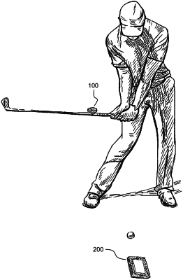
a laser device comprising a housing, a laser configured to emit a laser beam mounted in the housing, and a mounting device configured to mount the laser device to a shaft of an object, wherein:
the mounting device is rotatable 360° around the shaft of the object prior to being secured thereto, and wherein the housing is rotatable 360° around an axis of the laser device relative to the mounting device, with a position indicator of the laser device having position reference markings for indicating specific positions of the housing and thus the laser relative to the mounting device,
the laser device further comprises a controller and an inertial measurement unit (IMU), the controller configured to process signals from the IMU to determine an orientation of the laser beam emitted by the laser and to turn off the laser when the orientation of the laser beam exceeds a predetermined cutoff angle above downward vertical, and the predetermined cutoff angle is between 70° and 75°,
the mounting device of the laser device comprises a ring clamp, and the ring clamp is a single pin clamp with hinged ring portions and a swing arm closure, and
the object is a golf club, tennis racquet or baseball bat to be swung by a user;
a belt mount device comprising a clip body and two arms extending outward from the clip body, wherein the clip body has two attachment slots configured to receive a strap worn by a user, the attachment slots fully extend through the clip body in a horizontal direction, and the attachment slots partially extend through the clip body in a vertical direction beginning from a bottom of the clip body, and wherein the two arms carry a hollow mounting shaft which extends between the two arms at a distance from the clip body, whereby the hollow mounting shaft is configured for attaching the laser device thereon and for mounting a training rod therethrough; and
a ball marker device comprising a body having two sections of different vertical thickness when a bottom side of the ball marker device is placed on a horizontal surface, the two sections of different vertical thickness being a thinner section and a thicker section adjacent to the thinner section, wherein the thinner section includes one end of the ball marker device and the thicker section includes another end of the ball marker device, and wherein:
the thinner section is configured for placement of a golf ball thereon, with the thinner section having a hole extending therein, the hole configured for nesting the golf ball in place on the thinner section, whereby a putter golf club must be raised high enough to clear the thicker section during the swing motion in order to strike the golf ball placed on the thinner section,
the thinner section transitions into the thicker section along an interface, and the interface comprises a curved portion whose curvature increases an extension of the thinner section relative to the thicker section,
a top side of the body comprises guide markings including:
a circular placement indicator which visually indicates, in conjunction with the golf ball placed on the thinner section, when a user is in a desired putting stance, wherein the hole of the thinner section is located at a center of the circular placement indicator, and wherein, to indicate the desired putting stance, the circular placement indicator is configured such that the golf ball placed on the thinner section eclipses the circular placement indicator from a perspective of the user's non-dominant eye when the user closes his or her dominant eye in the desired putting stance,
a target line indicator which visually indicates a desired putting direction of the golf ball for the swing motion, wherein the target line indicator includes portions located in both the thinner section and the thicker section, and
a club face line indicator which visually indicates a desired square position of the putter golf club relative to the golf ball for the swing motion, wherein the club face line indicator is located in the thicker section and arranged perpendicular to the target line indicator,
a curved notch is formed into a top side edge of the thicker section opposite the thinner section, and
the thicker section is 5 mm thick, and the thinner section is 1.2 mm thick.
|