US 11,701,513 B2
Unwrapped 2D view of a stimulation lead with complex electrode array geometry
Steven M. Goetz, North Oaks, MN (US); Richard T. Stone, Minneapolis, MN (US); Warren W. Ball, Coon Rapids, MN (US); Carl D. Wahlstrand, North Oaks, MN (US); Michael T. Hegland, Mounds View, MN (US); Gabriela C. Molnar, Blaine, MN (US); and James M. Olsen, Plymouth, MN (US)
Assigned to Medtronic, Inc., Minneapolis, MN (US)
Filed by Medtronic, Inc., Minneapolis, MN (US)
Filed on May 22, 2020, as Appl. No. 16/881,907.
Application 16/881,907 is a continuation of application No. 16/517,316, filed on Jul. 19, 2019, granted, now 10,661,074.
Application 16/517,316 is a continuation of application No. 15/710,571, filed on Sep. 20, 2017, granted, now 10,556,103, issued on Feb. 11, 2020.
Application 15/710,571 is a continuation of application No. 14/954,298, filed on Nov. 30, 2015, granted, now 10,335,588, issued on Jul. 2, 2019.
Application 14/954,298 is a continuation of application No. 14/028,371, filed on Sep. 16, 2013, granted, now 9,199,090, issued on Dec. 1, 2015.
Application 14/028,371 is a continuation of application No. 13/592,918, filed on Aug. 23, 2012, granted, now 8,538,549, issued on Sep. 17, 2013.
Application 13/592,918 is a continuation of application No. 11/591,188, filed on Oct. 31, 2006, granted, now 8,380,321, issued on Feb. 19, 2013.
Claims priority of provisional application 60/785,181, filed on Mar. 23, 2006.
Claims priority of provisional application 60/776,454, filed on Feb. 24, 2006.
Prior Publication US 2020/0282205 A1, Sep. 10, 2020
This patent is subject to a terminal disclaimer.
Int. Cl. A61N 1/05 (2006.01); A61N 1/372 (2006.01); A61N 1/36 (2006.01)
CPC A61N 1/0534 (2013.01) [A61N 1/36157 (2013.01); A61N 1/36185 (2013.01); A61N 1/37247 (2013.01); A61N 1/36071 (2013.01)] 26 Claims
OG exemplary drawing
 
1. An external device comprising:
a display; and
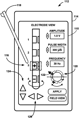
a processor configured to present, via the display, an array view of a representation of an implantable lead having a complex electrode array geometry, wherein:
the complex electrode array geometry comprises a first electrode located at a first axial position of a lead and a first angular position about a circumference of the lead, a second electrode located at the first axial position of the lead and a second angular position about the circumference of the lead different than the first angular position, and a third electrode located at the first axial position of the lead and a third angular position about the circumference of the lead different than the second angular position, and
the array view depicts a representation of the first electrode to a left side of a representation of the second electrode and depicts a representation of the third electrode to a right side of the representation of the second electrode.