| CPC A61M 1/1664 (2014.02) [A61M 1/28 (2013.01); A61M 2205/0233 (2013.01); A61M 2205/3368 (2013.01); A61M 2205/3538 (2013.01); A61M 2205/3633 (2013.01); A61M 2205/3673 (2013.01)] | 14 Claims |
|
1. A heating apparatus, comprising:
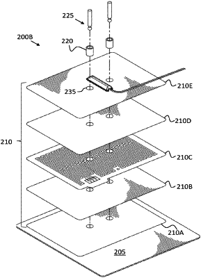
a heat source (210) having a top surface, a bottom surface, and an aperture (235) extending from the top surface, to the bottom surface, wherein the heat source (210) is a silicone heater stack comprising:
a first silicone-based layer (210A) thermally coupled to a heat transfer body;
a second silicone-based layer (210B) disposed on top of the first silicone-based layer;
a heating element layer (210C) disposed on top of the second silicone-based layer;
a third silicone-based layer (210D) disposed on top of the heating element layer;
a fourth silicone-based layer (210E) disposed on top of the third silicone-based layer,
the heat transfer body (205) thermally coupled with the heat source (210) and disposed proximate the bottom surface of the heat source (210), the heat transfer body (205) comprising a thermally conductive material;
a thermal insulating module (220) extending through the aperture (235) in the heat source (210), the thermal insulating module (220) comprising a cavity extending through the heat source (210);
a temperature sensor (225) inserted through the cavity of the thermal insulating module (220), the temperature sensor (225) being thermally coupled to the heat transfer body (205) and being thermally decoupled from the heat source (210), such that the temperature sensor (225) is thermally insulated from direct heating effects of the heat source (210); and,
a thermal breaker (230) thermally coupled to the heat source (210) and configured to shut off power to the heat source (210) when the heat source (210) exceeds a predetermined threshold for a predetermined time.
|