US 11,701,133 B2
Ankle replacement system and method
Shawn McGinley, Arlington, TN (US); Robert M. Howles, Barlett, TN (US); Daniel E. Free, Oakland, TN (US); Vinay D. Patel, Memphis, TN (US); Ramon Luna, Arlington, TN (US); and Matthew D. Schultz, Orlando, FL (US)
Assigned to WRIGHT MEDICAL TECHNOLOGY, INC., Memphis, TN (US)
Filed by Wright Medical Technology, Inc., Memphis, TN (US)
Filed on Jan. 14, 2022, as Appl. No. 17/648,030.
Application 17/402,760 is a division of application No. 15/982,337, filed on May 17, 2018, granted, now 11,116,524, issued on Sep. 14, 2021.
Application 17/648,030 is a continuation of application No. 17/402,760, filed on Aug. 16, 2021.
Application 15/982,337 is a continuation of application No. 14/448,242, filed on Jul. 31, 2014, granted, now 9,993,255, issued on Jun. 12, 2018.
Application 14/448,242 is a continuation of application No. PCT/US2014/027448, filed on Mar. 14, 2014.
Application PCT/US2014/027448 is a continuation in part of application No. 14/100,799, filed on Dec. 9, 2013, granted, now 9,480,571, issued on Nov. 1, 2016.
Claims priority of provisional application 61/846,831, filed on Jul. 16, 2013.
Claims priority of provisional application 61/782,507, filed on Mar. 14, 2013.
Claims priority of provisional application 61/746,393, filed on Dec. 27, 2012.
Prior Publication US 2022/0133337 A1, May 5, 2022
Int. Cl. A61B 17/17 (2006.01); A61B 17/15 (2006.01); A61B 17/16 (2006.01); A61F 2/42 (2006.01); A61F 2/46 (2006.01); A61F 2/30 (2006.01); A61B 90/00 (2016.01)
CPC A61B 17/1739 (2013.01) [A61B 17/15 (2013.01); A61B 17/1682 (2013.01); A61F 2/4202 (2013.01); A61F 2/4606 (2013.01); A61F 2/4637 (2013.01); A61F 2/4684 (2013.01); A61B 17/1703 (2013.01); A61B 17/1775 (2016.11); A61B 2090/3966 (2016.02); A61F 2002/30387 (2013.01); A61F 2002/30878 (2013.01); A61F 2002/4205 (2013.01); A61F 2002/4207 (2013.01); A61F 2002/4687 (2013.01)] 28 Claims
OG exemplary drawing
 
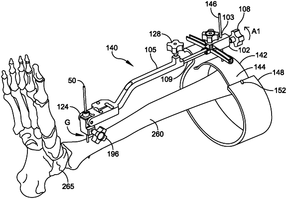
1. A system, comprising:
a first alignment guide, the first alignment guide including:
a first frame comprising:
a first elongate body extending from a first end to a second end,
a first knob is disposed adjacent to the first end of the first elongate body to facilitate locking the first frame to a first pin, and
a hinge disposed adjacent to the first end of the first elongate body, the hinge configured to permit at least a portion of the first elongate body to pivot about an axis that extends parallel to a coronal plane to permit at least the portion of the first elongate body to move in a sagittal plane;
a second frame comprising:
a second elongate body extending from a first end to a second end and defining a channel sized and configured to receive at least a portion of the first elongate body,
a second knob disposed at the first end of the second elongate body and configured to prevent relative movement between the first elongate body and the second elongate body, and
a third knob is disposed adjacent to the second end of the second elongate body to facilitate locking the second frame to a distal tibial pin.