| CPC H04N 23/52 (2023.01) [G03B 17/14 (2013.01); G03B 17/561 (2013.01); H04N 23/63 (2023.01)] | 11 Claims |

|
1. An imaging apparatus having an imaging element, a top side, a bottom side, a front side, and a rear side having an upper side, the imaging apparatus comprising:
exterior members;
a control circuit mounted on a control circuit board and configured to control the imaging apparatus;
a display panel disposed on the rear side as one of the exterior members; and
a heat release fan disposed on the bottom side as one of the exterior members,
wherein the control circuit board and the display panel are arranged sequentially in a direction of an optical axis from the front side to the rear side,
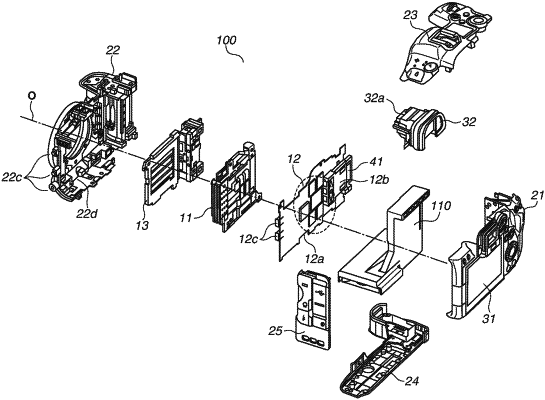
wherein a duct, that includes a duct rear side and a vent formed on an upper side of the duct rear side as one of the exterior members, extends in the optical axis direction from the rear side to the front side, extends in a direction from the top side to the bottom side in an area between the control circuit board and the display panel, and connects to a bottom side vent formed on the bottom side of the imaging apparatus as one of the exterior members, and
wherein the heat release fan is disposed inside the duct near the bottom side below the control circuit board.
|