| CPC H03K 4/026 (2013.01) [H03K 7/08 (2013.01); H03K 21/406 (2013.01)] | 20 Claims |

|
1. A circuit for generating ultrahigh-precision digital pulse signals, comprising:
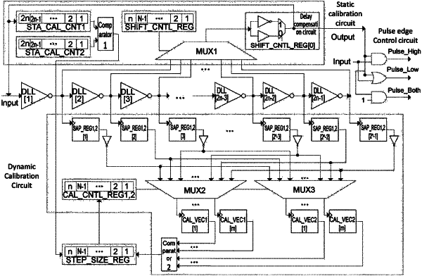
a pulse edge control circuit, used for delaying a signal on an input pin Input, controlling positions of a rising edge and a falling edge of a pulse signal, controlling the width of pulses, and generating ultrahigh-precision pulses; the pulse edge control circuit comprising a delay chain, a delay control circuit and a delay compensation circuit; the delay control circuit comprising a shift control register and a selector, and the shift control register controlling a number of delay cells through which the signal from the input pin Input passes before the signal reaches an output pin; and the delay compensation circuit being used to counteract the influence of an introduced delay;
a static calibration circuit, used for calculating step size information representing the relationship between a work clock period of a system and a delay of delay cells in the pulse edge control circuit when the system is powered on to work, and storing the step size information;
the static calibration circuit comprising:
a calibration counter;
a first comparator, for comparing values of the calibration counter to determine a step size;
a delay control circuit, which is the delay control circuit in the pulse edge control circuit; and
a delay compensation circuit, which is the delay compensation circuit in the pulse edge control circuit;
a dynamic calibration circuit, used for dynamically and real-time calculating the step size information when a rising edge or a falling edge of each pulse on the input pin Input arrives;
the dynamic calibration circuit comprising:
a sample circuit, used for recording an output value of each delay cell on the delay chain when a clock edge arrives;
a calibration control circuit, used for selecting two groups of continuous values from the sample circuit to form two calibration vectors; and
a second comparator, used for calculating a calibration position in each calibration vector to calculate the step size, wherein the calibration position is the position of the last delay cell, through which the signal from the input pin Input is propagated, on the delay chain when the sample circuit samples the output value of each delay cell on the delay chain.
|