| CPC H02K 1/276 (2013.01) [B60L 50/00 (2019.02); H02K 29/03 (2013.01)] | 17 Claims |

|
1. A rotor structure, comprising:
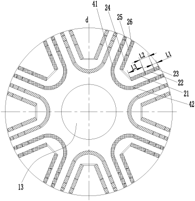
a rotor body provided with a permanent magnet slot group, the permanent magnet slot group comprising a permanent magnet slot, a first segment and a second segment of the permanent magnet slot being arranged to extend towards an outer edge of the rotor body, and an intermediate portion of the permanent magnet slot being arranged to protrude towards a side where a shaft hole of the rotor body is disposed;
a permanent magnet arranged in the permanent magnet slot, the permanent magnet comprising a plurality of permanent magnet segments, and partial lengths of the permanent magnet segments gradually decreasing outwards along a radial direction of the rotor body;
the permanent magnet slot comprises an inner layer permanent magnet slot and an outer layer permanent magnet slot; the inner layer permanent magnet slot and the outer layer permanent magnet slot are arranged and spaced outwards along the radial directions of the rotor body; the permanent magnet comprises an inner layer permanent magnet and an outer later permanent magnet; the inner layer permanent magnet is arranged in the inner layer permanent magnet slot; the outer layer permanent magnet is arranged in the outer layer permanent magnet slot; and the inner layer permanent magnet and the outer layer permanent magnet each comprise a plurality of permanent magnet segments;
The plurality of the permanent magnet segments comprise a first outer component segment, a second outer component segment and a third outer component segment; and the first outer component segment, the second outer component segment and the third outer component segment are arranged outwards along the radial direction of the rotor body in sequence and arranged in a first segment of the outer layer permanent magnet slot, and disposed at a first side of a direct-axis of the rotor body; a length of the third outer component segment in the radial direction of the rotor body is L1; length of a second outer component segment in the radial direction of the rotor body is L2; a length of the first outer component segment in the radial direction of the rotor body is L3; and L3>L2>L1.
|