| CPC G09G 3/342 (2013.01) [G09G 3/2007 (2013.01); G09G 2320/0233 (2013.01); G09G 2320/0626 (2013.01)] | 18 Claims |
|
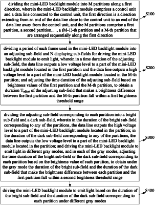
1. A method for driving a mini light emitting diode (mini-LED) backlight module, comprising steps of:
Step S100: dividing the mini-LED backlight module into M partitions along a first direction, wherein the mini-LED backlight module comprises a control unit and a data line connected to the control unit, the first direction is a direction extending from an end of the data line close to the control unit to an end of the data line away from the control unit, and the M partitions comprise a first partition, a second partition, . . . , a (M−1)-th partition and a M-th partition that are arranged sequentially along the first direction;
Step S200: dividing a period of each frame used in the mini-LED backlight module into an adjusting sub-field and N displaying sub-fields for driving the mini-LED backlight module to emit light, wherein in a time duration of the adjusting sub-field, the data line outputs a low voltage level to a part of the mini-LED backlight module located in the first partition and the data line outputs a high voltage level to a part of the mini-LED backlight module located in the M-th partition; and adjusting the time duration of the adjusting sub-field based on brightness values of the first partition and the M-th partition, to obtain a duration Tadjust of the adjusting sub-field that makes a brightness difference between the first partition and the M-th partition fall within a first brightness threshold range;
Step S300: dividing the adjusting sub-field corresponding to each partition into a bright sub-field and a dark sub-field, wherein in a duration of the bright sub-field corresponding to any of the partitions, the data line outputs the high voltage level to a part of the mini-LED backlight module located in the any of partitions; in a duration of the dark sub-field corresponding to any of the partitions, the data line outputs the low voltage level to a part of the mini-LED backlight module located in the any of partitions; and driving the mini-LED backlight module to emit light in different gray modes, and in each of the gray modes, adjusting a time duration of the bright sub-field or the dark sub-field corresponding to each partition based on the brightness value of each partition, to obtain under the gray mode a duration of the bright sub-field and a duration of the dark sub-field that make the brightness difference between each partition and the first partition fall within a second brightness threshold range; and
Step S400: driving the mini-LED backlight module to emit light based on a duration of the bright sub-field and a duration of the dark sub-field corresponding to each partition under different gray modes.
|