| CPC G06T 17/20 (2013.01) [B64C 39/024 (2013.01); G01N 21/64 (2013.01); G01N 21/8851 (2013.01); G01N 22/02 (2013.01); G01S 7/4817 (2013.01); G01S 13/89 (2013.01); G01S 15/89 (2013.01); G01S 17/86 (2020.01); G01S 17/89 (2013.01); G06F 30/13 (2020.01); G06Q 30/0278 (2013.01); G06Q 30/0283 (2013.01); G06Q 40/08 (2013.01); G06Q 50/16 (2013.01); G06Q 50/163 (2013.01); G06T 1/0007 (2013.01); G06T 7/0002 (2013.01); H04N 7/185 (2013.01); H04N 13/106 (2018.05); H04N 13/254 (2018.05); H04N 13/271 (2018.05); H04N 13/275 (2018.05); H04R 23/008 (2013.01); G01N 2201/06113 (2013.01); G01N 2201/10 (2013.01); G06T 2200/08 (2013.01); G06T 2207/10028 (2013.01); G06T 2207/10032 (2013.01)] | 20 Claims |
|
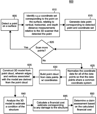
1. A computer-implemented method of inspecting a structure, the method comprising:
receiving, by one or more processors, data collected by an unmanned aerial vehicle (UAV) corresponding to points on a surface of a structure;
identifying, by the one or more processors, a plurality of coordinate sets associated with the UAV data, the coordinate sets each relating to vertical, horizontal, and depth distance measurements;
normalizing, by the one or more processors, the plurality of coordinate sets to share a common coordinate system; and
generating, by the one or more processors, a 3D point cloud for the structure, wherein the 3D point cloud is generated based at least in part on the received UAV data and the normalized plurality of coordinate sets.
|