| CPC G06F 30/20 (2020.01) [G06F 30/15 (2020.01); G06F 2111/10 (2020.01)] | 5 Claims |

|
1. A radiation effect shielding calculation method based on a three-dimensional spacecraft model, comprising:
step 1, obtaining the three-dimensional spacecraft model;
step 2, dividing a 4π space irradiation environment where the three-dimensional spacecraft model is located, into meshes to obtain space irradiation vectors corresponding to the meshes respectively and taking the space irradiation vectors as whole-space irradiation vectors;
wherein the step 2 comprises:
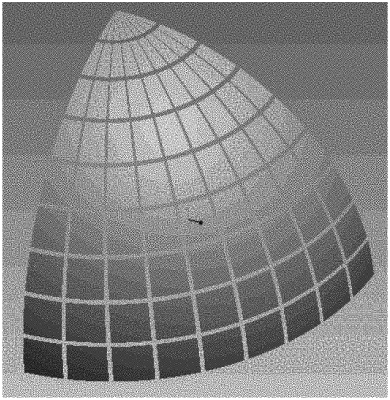
selecting a mesh division from a group consisting of an equal-angle mesh division with equal angles in longitude and latitude directions, an equal-area mesh division with equal angles in a longitude direction and equal heights in a latitude direction and an intelligent mesh division with equal angles in a longitude direction and equal heights in a latitude direction as well as mesh optimization in two poles;
setting numbers of longitudinal divisions and latitudinal divisions in the mesh division to divide the 4π space irradiation environment where the three-dimensional spacecraft model is located, into the meshes;
setting one or more analysis points at each of target model components in the three-dimensional spacecraft model by one of importing position coordinates of the one or more analysis points in batches and using a mouse to click positions at the target model components;
using a ray tracing method, using each of the analysis points of the target model components as a starting point, assigning the meshes irradiation vectors that pass through geometrical centers of the meshes corresponding thereto and cover model entities, with each the analysis point as a center and outward directions, of the three-dimensional spacecraft model, to obtain the space irradiation vectors corresponding to the meshes respectively, and taking the space irradiation vectors as the whole-space irradiation vectors corresponding to each the analysis point;
step 3, inputting the whole-space irradiation vectors corresponding to each the analysis point to the three-dimensional spacecraft model to perform shielding calculation by a shielding thickness calculation method, selecting one of a slant method, a norm method and a weight method according to a type of radiation particles to obtain a three-dimensional distribution of actual shielding thicknesses at each the analysis point, and performing an equivalent thickness conversion for different materials to obtain a three-dimensional distribution of equivalent aluminum shielding thicknesses including different directions and solid angles of each the analysis point;
wherein the step 3 comprises:
inputting the whole-space irradiation vectors corresponding to each the analysis point to the three-dimensional spacecraft model to perform the shielding calculation by the shielding thickness calculation method, obtaining position coordinates (xi, yi, zi) of an intersection of an ith space irradiation vector and the target model component in the three-dimensional spacecraft model, calculating a distribution d={d1, d2, d3, . . . , dn} of actual intersection thicknesses of actual rays in directions of the space irradiation vectors and the target model components in the three-dimensional spacecraft model, wherein each the actual intersection thickness is calculated by the following formula:
 wherein di represents the actual intersection thickness of the actual ray in the direction of the ith space irradiation vector and the target model components in the three-dimensional spacecraft model; k represents a quantity of the target model components, which intersect with the ith space irradiation vector; xj1 represents the position coordinates (xi1, yi1, zi1) of the intersection of the actual ray incident on a jth target model component; xj2 represents the position coordinates (xj2, yj2, zj2) of the intersection of the actual ray emergent on the jth target model component;
selecting the one of the slant method, the norm method and the weight method according to the type of radiation particles to work out the distribution d={d1, d2, d3, . . . , dn} of actual intersection thickness to obtain the three-dimensional distribution of actual shielding thicknesses at each the analysis point;
wherein the slant method comprises: obtaining a three-dimensional distribution dz={d1, d2, d3, . . . , dn} of actual shielding thicknesses at each the analysis point by the actual rays propagating along a straight line in the target model components;
wherein the norm method comprises: obtaining a three-dimensional distribution df={d1×cos α1, d2×cos α2, d3×cos α3, . . . , dn×cos αi} of actual shielding thicknesses at each the analysis point by the actual rays propagating along a normal direction of an incident point into a surface when the actual rays shoot into the target model components; wherein αi represents an incident angle, and i=1, . . . , n;
wherein the weight method comprises: obtaining a three-dimensional distribution
 angle and αi2 represents an emergent angle, and i=1, . . . , n;
converting the actual shielding thickness at each the analysis point to the equivalent aluminum shielding thicknesses according to material properties of model components to as the equivalent aluminum shielding thicknesses of the space irradiation vectors respectively, and combining the equivalent aluminum shielding thicknesses of the space irradiation vectors corresponding to each the analysis point to obtain the three-dimensional distribution of the equivalent aluminum shielding thicknesses including the different directions and the solid angles of each the analysis point;
step 4, calculating residual irradiation effect values of the three-dimensional distribution of the equivalent aluminum shielding thicknesses of each the analysis point according to an acquired radiation effect curve to obtain detailed irradiation data of a three-dimensional distribution of irradiation effect values of each the analysis point; and
step 5, performing information post processing on the detailed irradiation data of the three-dimensional distribution of the irradiation effect values of each the analysis point to generate and display a two-dimensional cloud image, a three-dimensional cloud image, a three-dimensional ray diagram and a detailed three-dimensional distribution statement of radiation effect, and integrating the detailed radiation data of the three-dimensional distribution of the irradiation effect values of each the analysis point in all directions to obtain a total radiation effect value of each the analysis point to evaluate an irradiation effect of each the analysis point.
|