| CPC G03G 21/105 (2013.01) [G03G 15/0865 (2013.01); G03G 15/0893 (2013.01); G03G 15/1615 (2013.01); G03G 21/12 (2013.01); G03G 21/1647 (2013.01); G03G 2221/1624 (2013.01)] | 10 Claims |

|
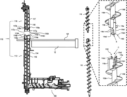
1. A toner conveying device for conveying toner, comprising:
a first conveying portion configured to convey the toner; and
a second conveying portion configured to convey the toner conveyed from the first conveying portion,
wherein the first conveying portion includes:
a first screw that is rotatable around a first rotational axis and includes a first rotation shaft and a first blade portion which has a helix shape with the first rotational axis as a helical axis and which is disposed on an outer peripheral surface of the first rotation shaft, the first screw including, in a first end portion of the first rotation shaft in a direction of the first rotational axis, an engaging portion, and a first protruded portion which is protruded from the first rotation shaft in a direction intersecting with the first rotational axis; and
a first conveying passage forming member having a first inner wall face which forms a first conveying passage inside which the first screw is disposed, the first inner wall face extending in the direction of the first rotational axis, so as to overlap with the first protruded portion when viewed in a direction orthogonal to the first rotational axis,
wherein the second conveying portion includes:
a second screw that is rotatable around a second rotational axis and includes a second rotation shaft and a second blade portion which has a helix shape with the second rotational axis of the second rotation shaft as a helical axis and which is disposed on an outer peripheral surface of the second rotation shaft, the second screw including, in a second end portion of the second rotation shaft in a direction of the second rotational axis, an engaged portion, which engages with the engaging portion of the first screw so that the second screw is rotated by the rotation of the first screw, and a second protruded portion which is protruded from the second rotation shaft in a direction intersecting with the second rotational axis; and
a second conveying passage forming member having a second inner wall face which forms a second conveying passage inside which the second screw is disposed, the second conveying passage forming member being connected with the first conveying passage forming member, the second inner wall face extending in the direction of the second rotational axis, so as to overlap with the second protruded portion when viewed in a direction orthogonal to the second rotational axis,
wherein the first protruded portion is a third blade portion which has a helix shape with the first rotational axis as the helical axis and which is disposed on the outer peripheral surface of the first rotation shaft so as to have a first phase difference from the first blade portion in a rotation direction of the first rotation shaft, and
wherein the second protruded portion is a fourth blade portion which has a helix shape with the second rotational axis as the helical axis and which is disposed on the outer peripheral surface of the second rotation shaft so as to have a second phase difference from the second blade portion in a rotation direction of the second rotation shaft.
|