| CPC G03B 17/561 (2013.01) [F16M 13/022 (2013.01); F16M 11/10 (2013.01); F16M 11/2014 (2013.01)] | 20 Claims |

|
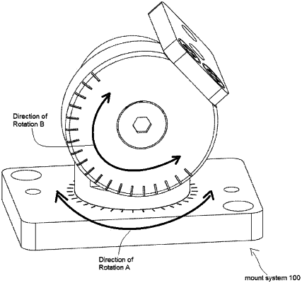
1. A method of manufacturing a mount system, comprising:
fabricating a rectangular base with a two-sided center aperture;
fabricating a lower swivel with a circular bottom fitted to be located within an upper side of the center aperture;
fabricating a disc-shaped puck to fit within a lower side of the center aperture;
fabricating the lower swivel to have a conical-shaped tapered aperture in a vertical side; and
fabricating an upper swivel to have a conical-shaped tapered protrusion that matches with the conical-shaped tapered aperture in the lower swivel.
|