| CPC G02B 6/3831 (2013.01) [G02B 6/3882 (2013.01)] | 20 Claims |

|
1. A fiber optic connector comprising:
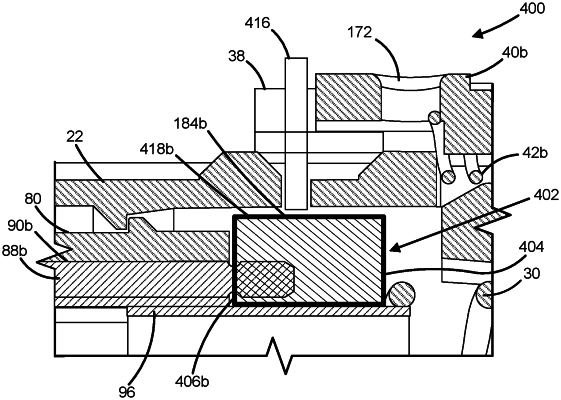
a connector body defining a longitudinal axis, the connector body having opposing major sides and minor sides, and a pin release opening is defined on each of the minor sides;
a multi-fiber ferrule disposed at least partially within the connector body and configured to receive a plurality of optical fibers, the multi-fiber ferrule defining a pair of alignment pin openings that extend along the longitudinal axis;
a sleeve body slidably mounted on the connector body;
a pair of alignment pins, each alignment pin having a circumferential groove; and
a pin retention structure disposed within the connector body and adjacent the multi-fiber ferrule, the pin retention structure configured to releasably secure each of the pair of alignment pins at least partially within a respective alignment pin opening of the pair of alignment pin openings to define a gender of the fiber optic connector, the pin retention structure comprising:
a main body; and
a pair of pin retainers supported by the main body, each pin retainer axially aligned with the respective alignment pin opening, and each pin retainer comprising:
opposing resilient elements extending along the longitudinal axis and having free ends configured to engage with opposing sides of a respective alignment pin at the circumferential groove, the opposing resilient elements positioned proximate a respective pin release opening on the minor side of the connector body,
wherein when the sleeve body slides rearward, the pin release openings of the connector body are uncovered allowing receipt of a tool to access each of the pair of pin retainers via the pin release openings and directly contact the opposing resilient elements at a location spaced from the free end to flex away from each other in a direction that is substantially orthogonal to the longitudinal axis to release the respective alignment pin.
|