| CPC G01N 23/046 (2013.01) [G01N 1/28 (2013.01)] | 8 Claims |

|
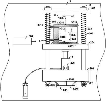
1. A hydro-mechanical coupling experimental device with computed tomography (CT) real-time scanning, comprising a CT scanning room wherein the device further comprises a support frame, a hydro-mechanical coupling mechanism and a jack that are arranged in the CT scanning room;
the support frame comprises a base, a top plate, a plurality of columns for arranging the top plate and the base at intervals, and a movable plate that is arranged between the top plate and the base and capable of sliding on the plurality of columns; the hydro-mechanical coupling mechanism comprises an experimental box, a pressure box arranged inside the experimental box and a compression leg slidingly worn on a top of the experimental box; and the experimental box is arranged on the movable plate, and the jack is arranged on the base;
the hydro-mechanical coupling mechanism further comprises a regulating assembly, and the regulating assembly comprises an operation block, a first threaded rod and two first limiting members; and
one end, located in the experimental box, of the compression leg is provided with a first installation groove, screws at two sides of the first threaded rod are symmetrically arranged, two ends of the first threaded rod are rotationally arranged on groove walls of two sides of the first installation groove in respective, and one end of the first threaded rod passes through the first installation groove and the compression leg to be connected to the operation block; and the two first limiting members are in threaded connection with the two sides of the first threaded rod in respective, and the two first limiting members are slidingly connected to the groove wall of the first installation groove in respective.
|