|
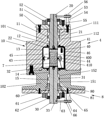
1. A pressure-preserving conventional triaxial compression loading apparatus, comprising: a pressure vessel, an upper piston rod, a lower piston rod, and an annular oil bag assembly, wherein the pressure vessel is formed by connecting an upper cylinder block and a lower cylinder block using bolts in a sealed manner, an upper annular boss is disposed on the upper piston rod, an annular area of the upper annular boss is equal to a cross-sectional area of the upper piston rod, a lower annular boss is disposed on the lower piston rod, an annular area of the lower annular boss is equal to a cross-sectional area of the lower piston rod, hollow chambers of the pressure vessel in vertical communication sequentially comprise an upper chamber, an upper sealed chamber, a confining pressure chamber, a lower sealed chamber, and a lower chamber from top to bottom, an upper cylinder cover is fixedly sealed on an upper end surface of the pressure vessel, the upper annular boss fits the upper chamber in a sealed manner, the upper piston rod located below the upper annular boss fits the upper sealed chamber in a sealed manner, the upper piston rod located above the upper annular boss passes upward through the upper cylinder cover to fit the upper cylinder cover in a sealed manner, the upper annular boss of the upper piston rod divides the upper chamber into two chambers independent of each other, the two chambers are an upper balance chamber located above the upper annular boss and an upper compensation chamber located below the upper annular boss, a lower port of the lower chamber of the pressure vessel is provided with a lower sealing assembly fitting the lower port in a sealed manner, a lower cylinder cover is fixed on a lower end surface of the pressure vessel, the lower piston rod located above the lower annular boss fits the lower sealed chamber in a sealed manner, the lower annular boss fits the lower chamber in a sealed manner, the lower piston rod located below the lower annular boss sequentially passes downward through an inner hole of the lower sealing assembly and the lower cylinder cover, the lower piston rod fits the inner hole of the lower sealing assembly in a sealed manner, the lower annular boss of the lower piston rod divides the lower chamber into two chambers independent of each other, the two chambers are a lower balance chamber located below the lower annular boss and a lower compensation chamber located above the lower annular boss, the annular oil bag assembly is placed in the confining pressure chamber, the annular oil bag assembly comprises an oil bag support and an annular oil bag fixed in the oil bag support, the oil bag support is inserted in a concave groove that is in an inner wall of the confining pressure chamber and fits the oil bag support, when an annular inner chamber of the annular oil bag is filled with medium, an outer wall of the annular oil bag and the inner wall of the confining pressure chamber are attached together, a fidelity specimen is placed in a specimen chamber defined by a lower end surface of the upper piston rod, an upper end surface of the lower piston rod, and an inner wall of the annular oil bag, a variety of measuring sensors are disposed in the annular inner chamber of the annular oil bag, and the annular inner chamber, the specimen chamber, the upper balance chamber, the upper compensation chamber, the lower balance chamber, and the lower compensation chamber are chambers independent of each other and are separately provided with independent inlet and outlet pipes.
|
