| CPC F16K 17/065 (2013.01) [E03B 11/08 (2013.01); F15D 1/06 (2013.01)] | 5 Claims |
|
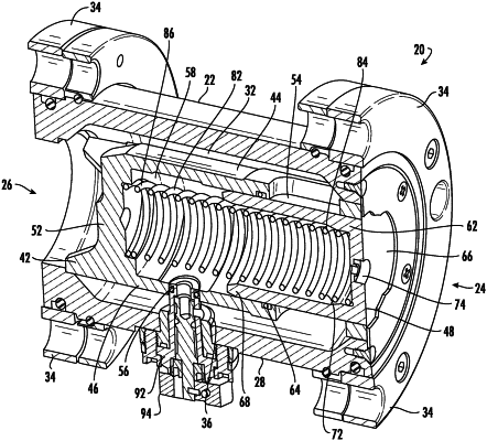
1. A hydrostatically adjustable flow valve (20) comprising:
a cylindrical outer housing (22) including an inlet (24), and outlet (26), a bottom portion (28), and an interior area (32), flanges positioned (34) about the inlet (24) and the outlet (26), a first outlet port (36) formed through the bottom portion (28);
a cylindrical fixed sleeve (42) including an outer wall (44), and a bottom portion (46), the cylindrical fixed sleeve (42) positioned within the interior area (32) of the cylindrical outer housing (22), the cylindrical fixed sleeve (42) including a first opened end (48) positioned adjacent the inlet (24) and a second closed end (52) positioned adjacent the outlet (26), at least one flow port (54) formed through the outer wall (44) at a location proximate the first end (48), the flow port (54) being fluidly interconnected to the outlet (26), a second outlet port (56) formed through the bottom portion (46), the cylindrical fixed sleeve (42) defining an interior area (58);
a spool (62) slidably positioned within the first opened end (48) of the cylindrical fixed sleeve (42), the spool (62) having first closed end (66), an opened second end (68), and an interior area (72), a primary orifice (74) formed within the first closed end (66), the spool (62) having a first orientation with the first end (66) of the spool (62) is flush with the first end (48) of the cylindrical fixed sleeve (42) to thereby close the flow port (54), and a second orientation wherein the first end (66) of the spool (62) is positioned at a location inward of the first end (48) of the of the cylindrical fixed sleeve (42) to thereby partially open the flow port (54);
a coil spring (82) having first and second ends (84 and 86), with the first end (84) of the spring (82) positioned within the interior area (72) of the spool (62) and the second end (86) positioned within the interior area (58) of the cylindrical fixed sleeve (42), the spring (82) biasing the spool (62) to the first orientation;
a control device (92) fluidly interconnected to the first and second outlet ports (36 and 56), the control device (92) including a dial means (94) for selectively varying the rate at which fluid drains from the interior areas (58 and 72) of the cylindrical fixed sleeve and spool (42 and 62), whereby draining the fluid results in the spool (62) attaining the second orientation and allowing the fluid to flow through the flow port (54) and the outlet (26).
|