| CPC E21B 43/261 (2013.01) [E21B 43/267 (2013.01); E21B 2200/20 (2020.05)] | 6 Claims |

|
1. A method for realizing uniform stimulation for an oil and gas well comprising a wellbore by multi-stage fracturing, comprising the following steps:
Step 1: Calculating and predicting the inlet widths of a fracture wi created in a planned hydraulic fracturing treatment, with Equation (1);
 Where: wi is an inlet width of the fracture, in m; E is Young's modulus of reservoir rock, in MPa; Q is a pump rate of a fracturing fluid, in m3/s; μ is a viscosity of the fracturing fluid, in MPa·s; v is the Poisson's ratio of the reservoir rock, dimensionless; h is a reservoir thickness, in m; and t is a fracturing time, in s;
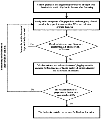
Step 2: Designing a plugging scheme for blocking the fracture inlet after each fracturing treatment; wherein selected plugging particles are composed of skeleton particles and filling particles; the filling particles are a soluble fluid diverting agent, and the filling particles diameter is less than 1/3 of that of the skeleton particles; the filling particles and the skeleton particles are respectively taken for fine screening to determine their particle diameter composition and classify as different kinds; and calculating the harmonic mean of diameters for the particles according to Equation (2), as the average diameter of the plugging particles:
 Where: a is an average diameter of the plugging particles, in m; bn is a particle diameter of n-th kind of skeleton particles, in m; vn is a volume fraction of n-th kind of skeleton particles among all the skeleton particles, dimensionless; cm is a particle diameter of m-th kind of filling particles, in m; gm is a volume fraction of m-th kind of filling particles among all the filling particles, dimensionless; and T is a volume fraction of the filling particles in the plugging particles, dimensionless;
Step 3: Checking whether the average particle diameter a is greater than 1/5 of the inlet width of fracture calculated in Step 1:
 If the conditions in Equation (3) are met, the average particle diameter a is selected as an optimized average particle diameter for plugging, and its corresponding particle composition is selected as an optimized particle composition; if the conditions in Equation (3) are not met, larger skeleton particles will be reelected, and the average particle diameter of plugging particles will be recalculated according to Step 2 until the conditions in Equation (3) are met;
Step 4: Calculating an optimized volume fraction Co of plugging particles required for blocking the fractures:
 Where: α is the average diameter of plugging particles, in m; and wi is the inlet width of fracture, in m;
Step 5: Based on the optimized particle composition and the optimized volume fraction Co , using a hydraulic fracturing model to simulate a fracturing and plugging process and checking whether the volume fraction of particles in the fracture near the wellbore can reach 60%; if the volume fraction fails to reach 60%, larger skeleton particles will be reelected, and Steps 2-5 are repeated until the volume fraction of particles in the fracture near the wellbore can reach 60% in the simulation;
Step 6: After completing the design of the plugging scheme, performing the planned fracturing treatment to create hydraulic fracturing in the reservoir;
Step 7: When the injection amount of fracturing fluid reaches 80-85% of the designed volume, pumping the plugging particles according to the optimized design to block the fracture; After successful plugging, performing a next fracturing treatment for a subsequent perforation cluster;
Step 8: Repeat Steps 1-7 until fracturing of all perforation clusters in the oil and gas well is completed;
Step 9: If necessary, treatment fluid is injected into the wellbore to dissolve the filling particles at the fracture inlet to recover a flow channel between each fracture with the wellbore.
|