| CPC E05B 65/462 (2013.01) [E05B 65/5215 (2013.01); E05B 47/0001 (2013.01); E05B 47/06 (2013.01); E05C 3/12 (2013.01)] | 6 Claims |

|
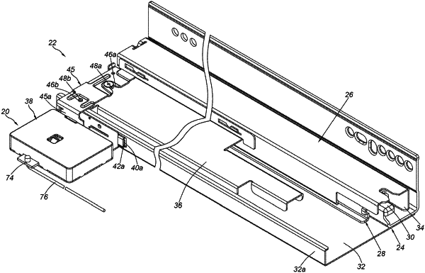
1. A slide rail system, comprising:
a slide rail assembly having a first rail and a second rail movable relative to each other along a longitudinal direction of the first rail and the second rail;
a lock mechanism mounted on the first rail or the second rail, the lock mechanism comprising:
a driving device comprising a motor;
a driving member connected to a shaft of the motor;
a linkage member configured to be driven by the driving member to be linearly moved in response to a rotational driving force of the motor; and
a locking member fixed to the linkage member in a non-rotatable manner and configured to be driven by the motor of the driving device through the linkage member to linearly move between a first position and a second position in a non-rotatable manner along a direction substantially perpendicular to the longitudinal direction of the first rail and the second rail, wherein the linkage member and the locking member can be seen as one piece; and
a fitting member detachably connected to the other one of the first rail and the second rail, wherein an additional feature is provided on an extension wall of the fitting member to interact with a locking part of the locking member;
wherein when the locking member is located at the first position, the locking member is configured to interact with the additional feature to lock the other one of the first rail or the second rail;
wherein when the locking member is located at the second position, the locking member does not lock the other one of the first rail or the second rail;
wherein a linear moving direction of the linkage member is substantially perpendicular to a rotation axis of the shaft of the motor;
wherein the lock mechanism further comprises a housing, wherein the linkage member and the housing have corresponding structural features including a protrusion and an elongated hole interacting with each other for guiding the linkage member to linearly move relative to the housing within a limited range defined by the corresponding structural features.
|