| CPC E02F 9/2242 (2013.01) [E02F 9/2285 (2013.01); E02F 9/2292 (2013.01); E02F 9/2296 (2013.01); F15B 11/165 (2013.01); F15B 11/17 (2013.01); E02F 9/2235 (2013.01); E02F 9/2267 (2013.01); F15B 2211/3144 (2013.01); F15B 2211/351 (2013.01); F15B 2211/455 (2013.01)] | 5 Claims |

|
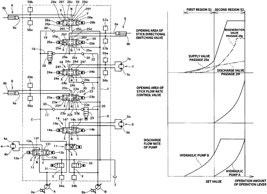
1. A hydraulic control system equipped with first, second hydraulic pumps; a first hydraulic actuator whose hydraulic supply source is both the first, second hydraulic pumps; and other hydraulic actuators whose hydraulic supply sources are at least one of the first, second hydraulic pumps, the hydraulic control system further comprising:
a first hydraulic actuator directional switching valve that has a supply valve passage and a discharge valve passage to and from the first hydraulic actuator and switches between supply and discharge directions;
a main-side supply oil passage, a sub-side supply oil passage that connects the first, second hydraulic pumps to pump ports of the first hydraulic actuator directional switching valve, respectively;
a first hydraulic actuator flow rate control valve that is placed at the sub-side supply oil passage, and controls a supply flow rate from the second hydraulic pump to the first hydraulic actuator directional switching valve; and
a control means for electronically controlling the first hydraulic actuator directional switching valve and the first hydraulic actuator flow rate control valve, wherein the first hydraulic actuator flow rate control valve is configured such that in a state where the first hydraulic actuator flow rate control valve is closing the sub-side supply oil passage, only a supply flow rate from the first hydraulic pump via the main-side supply oil passage is supplied to the first hydraulic actuator directional switching valve, and in a state where the first hydraulic actuator flow rate control valve is opening the sub-side supply oil passage, a control flow rate from the second hydraulic pump whose flow rate has been controlled by the first hydraulic actuator flow control valve and the supply flow rate from the first hydraulic pump are supplied to the first hydraulic actuator directional switching valve; and on the other hand,
wherein the first hydraulic actuator directional switching valve is a spool valve having a spool that is moved in proportion to an operation amount of a first hydraulic actuator operation lever, and is configured, in a first region of the former half of the spool stroke, to perform a supply flow rate control in accordance with an opening area of the supply valve passage that is increased or decreased depending on a spool stroke amount, and at a second region of the latter half of the spool stroke, to supply the flow rate input to a pump port to the first hydraulic actuator as it is without performing the supply flow rate control, since the opening area of the supply valve passage is set wider than when the supply flow rate control is performed; on the other hand, to perform a discharge flow rate control in accordance with an opening area of the discharge valve passage that is increased or decreased depending on the spool stroke amount in both the first and second regions; as well as,
wherein the control means is configured, in case where only the supply flow rate from the first hydraulic pump is sufficient for the supply flow rate to the first hydraulic actuator, to cause the sub-side supply oil passage to be closed by the first hydraulic actuator flow rate control valve, as well as to cause the spool of the first hydraulic actuator directional switching valve to be positioned at the first region, to perform the supply flow rate control from the first hydraulic pump to the first hydraulic actuator in accordance with an opening area of the supply valve passage of the first hydraulic actuator directional switching valve; on the other hand, in case where the supply flow rate to the first hydraulic actuator requires the flow rates from both the first and second hydraulic pumps, then to control the first hydraulic actuator flow rate control valve so that the supply flow rate from the second hydraulic pump to the first hydraulic actuator directional switching valve is increased in proportion to an operation amount of the first hydraulic actuator operation lever, and to cause the spool of the first hydraulic actuator directional switching valve to be positioned at the second region, to allow a total flow rate of the control flow rate from the second hydraulic pump controlled by the first hydraulic actuator flow rate control valve and the supply flow rate from the first hydraulic pump to be supplied to the first hydraulic actuator via the supply valve passage of the first hydraulic actuator directional switching valve.
|