| CPC E01C 23/088 (2013.01) | 16 Claims |

|
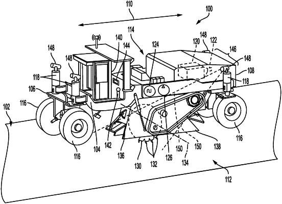
1. A milling machine comprising:
a frame supported on a plurality of traction devices for travel along a work surface with respect to a travel axis, the frame defining a first lateral side and a second lateral side of the milling machine parallel with the travel axis of the milling machine;
a cutting rotor rotatably supported on the frame for milling a work surface, the cutting rotor shaped as a cylindrical drum defining a rotor axis perpendicular to the travel axis;
an rotor enclosure supported on the frame to accommodate the cutting rotor, the rotor enclosure including a first enclosure sidewall aligned with the first lateral side and a second enclosure sidewall aligned with the second lateral side;
a camera supported on the frame at the first lateral side in a location to capture a visual image of the rotor enclosure and the work surface; and
an electronic controller being programmed to receive the visual image from the camera; receive data representing vertical rotor elevation; receive machine dimensional data including a rotor diameter; determine by kinematic equations positions for one or more lateral contact lines of the cutting rotor with respect to the work surface using the data representing vertical rotor elevation and the machine dimensional data, the lateral contact lines being generally perpendicular to the travel axis and generally parallel to the rotor axis; generate a reference line augmentation corresponding to the lateral contact lines; and superimpose the reference line augmentation on the visual image to create an augmented image.
|
|
11. A method of operating a milling machine comprising:
capturing a visual image of a lateral side of a rotor enclosure of the milling machine and a work surface to be milled by a cutting rotor accommodated in the rotor enclosure;
receiving data representing vertical rotor elevation;
receiving machine dimensional data including a rotor diameter;
determining by kinematic equations one or more lateral contact lines where the cutting rotor will contact the work surface using the data representing vertical rotor elevation and the machine dimensional data;
generating a reference line augmentation corresponding to the lateral contact lines;
superimposing the reference line augmentation on the visual image to create an augmented image; and
displaying the augmented image on a visual display associated with the milling machine.
|